Radar Level Sensor Types
Radar Level Sensor Types: A Comprehensive Engineering Guide to Selection and Application
In industrial process automation, accurate level measurement is critical for inventory management, process safety, and operational efficiency. Among the various technologies available, radar level measurement has emerged as a gold standard due to its non-contact nature and its ability to withstand harsh process conditions. However, selecting the correct equipment requires a deep understanding of the various radar level sensor types and their specific operating principles.
This guide examines the technical distinctions between radar technologies, providing engineers and procurement professionals with the factual framework necessary to specify the right instrument for water treatment, chemical processing, and oil and gas applications.
Measurement Principles of Radar Level Meters
Before categorizing specific sensor types, it is essential to understand how radar technology interacts with a process medium. Radar level instruments operate by emitting electromagnetic waves (microwaves) that travel at the speed of light. When these waves encounter a medium with a different dielectric constant ($ε_r$) than the atmosphere (usually air), a portion of the energy is reflected back to the sensor.
There are two primary methods used to calculate the distance based on these reflections:
1. Pulse Radar (Time of Flight)
Pulse radar sensors emit a short microwave signal and then switch to receiving mode. The instrument measures the time elapsed between the emission of the pulse and the reception of the echo. Since the speed of light is constant, the distance is calculated as:
*Distance = (Speed of Light × Travel Time) / 2*
Pulse radar is known for its energy efficiency and is often used in battery-powered or loop-powered applications. However, it may have limitations in high-precision requirements compared to frequency-modulated systems.
2. Frequency Modulated Continuous Wave (FMCW)
FMCW radar does not emit pulses. Instead, it transmits a continuous signal with a frequency that varies linearly over time (a frequency sweep). When the reflected signal is received, it is compared to the signal being transmitted at that exact moment. The frequency difference (Δf) between the transmitted and received signals is directly proportional to the distance. FMCW is generally more accurate and provides better signal-to-noise ratios, making it the preferred choice for complex industrial environments.
For a detailed look at hardware configurations using these principles, you can Review product options and application support from specialized manufacturers.
Primary Radar Level Sensor Types
Industrial radar sensors are broadly classified into two categories based on how the signal is transmitted to the medium: Non-contact (Free-space) radar and Guided Wave Radar (GWR).
Non-Contact Radar Level Sensors
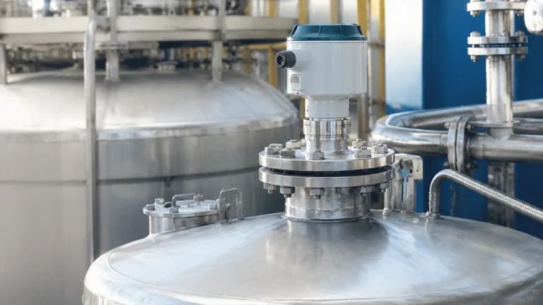
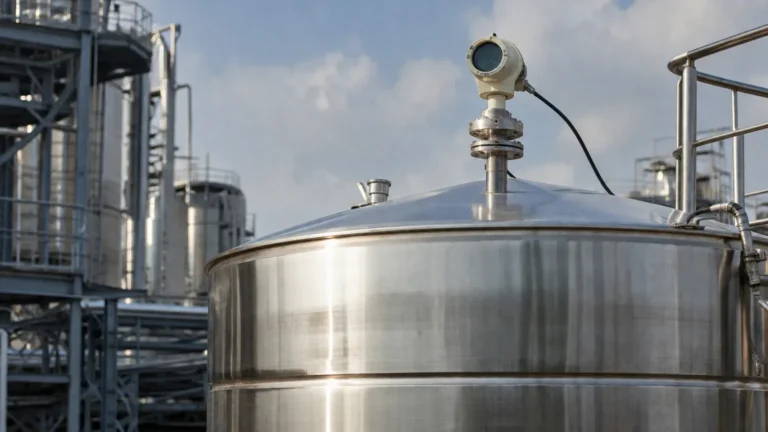
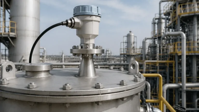
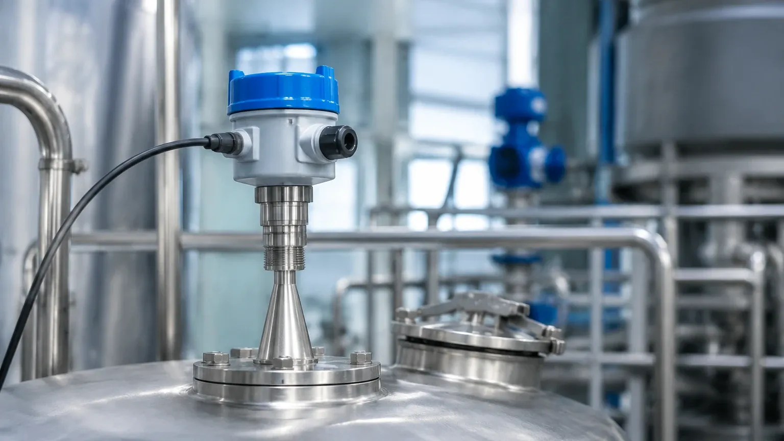
Non-contact Radar Level Meters are mounted at the top of a vessel and transmit microwaves through the air (or vapor space) to the surface of the material. They are ideal for corrosive, hygienic, or extremely hot materials because no part of the sensor touches the process media.
* 6 GHz Radar: Older technology with a wide beam angle. It is highly resistant to foam and heavy vapors but requires large nozzles and is prone to interference from tank internals.
* 26 GHz Radar: The industrial workhorse. It offers a narrower beam than 6 GHz models, allowing for use in medium-sized tanks with some internal obstructions. It balances cost and performance effectively.
* 80 GHz Radar: The modern standard for precision. With a very high frequency, the beam angle is extremely narrow (often as low as 3 degrees). This allows the sensor to avoid agitators, ladders, and narrow nozzles, and provides superior performance on low-dielectric liquids.
Guided Wave Radar (GWR)
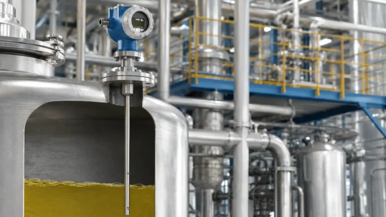
Guided Wave Radar uses a physical probe (a rod, cable, or coaxial tube) to guide the microwave signal directly to the medium. This technology is based on Time Domain Reflectometry (TDR).
* Advantages: Since the signal is concentrated along the probe, GWR is unaffected by tank geometry, foam, dust, or heavy turbulence. It is exceptionally reliable for materials with low dielectric constants.
* Limitations: Because the probe is in constant contact with the medium, it is subject to corrosion, coating (buildup), and mechanical stress from moving fluids or solids.
Technical Comparison and Selection Criteria
Choosing between these radar level sensor types depends on the physical properties of the media and the vessel constraints. The following table summarizes the key selection factors:
| Feature | Non-Contact (80 GHz) | Non-Contact (26 GHz) | Guided Wave Radar (GWR) |
| :— | :— | :— | :— |
| Measurement Range | Up to 120m | Up to 30m – 70m | Up to 30m (cable) |
| Accuracy | ±1mm to ±2mm | ±3mm to ±5mm | ±2mm to ±5mm |
| Beam Angle | Very Narrow (3°-8°) | Medium (10°-20°) | N/A (signal follows probe) |
| Impact of Foam | Moderate (can penetrate light foam) | Moderate | Minimal (highly resistant) |
| Internal Obstructions | Easily avoided | May cause interference | Ignored (if probe clears them) |
| Dielectric Constant (ε_r) | ≥ 1.4 | ≥ 1.6 | ≥ 1.2 |
| Installation | Top-mounted, easy | Top-mounted | Requires probe immersion |
Installation Considerations and Best Practices
Even the most advanced radar level sensor will fail if installed incorrectly. Engineers should adhere to the following guidelines to ensure signal integrity:
1. Nozzle Height and Diameter: For non-contact radar, the antenna should ideally extend slightly beyond the bottom of the mounting nozzle to prevent "ringing" or false echoes from the nozzle edge. 80 GHz sensors are more forgiving of tall nozzles due to their narrow beam.
2. Dead Zones (Blocking Distance): Every radar sensor has a minimum detection distance near the antenna (typically 50mm to 200mm). The maximum level of the tank must never enter this zone, or the sensor will lose the signal.
3. Avoid Obstructions: Ensure the signal path is clear of agitator blades, heating coils, and ladders. If an obstruction is unavoidable, many modern meters offer "False Echo Suppression" software to map out and ignore these static reflections.
4. Mounting Angle: The sensor must be mounted perpendicular to the liquid surface. For solid materials, an aiming flange (swivel mount) may be required to align the sensor with the angle of repose of the material.
5. Positioning: Never mount a radar sensor in the center of a tank (unless it is a spherical or domed tank where focal points are a concern) or directly above the filling inlet, as the turbulence and falling material will disrupt the signal.
Limitations and Application Risks
While versatile, radar technology faces specific physical limitations:
* Low Dielectric Media: Materials like liquid nitrogen, liquid petroleum gas (LPG), or certain solvents have very low dielectric constants. They reflect very little energy. In these cases, GWR or high-frequency 80 GHz radar with specialized sensitivity is required.
* Heavy Surface Foam: While radar can penetrate some foam, extremely dense, thick foam (like that found in some chemical reactors) can absorb the microwave signal entirely, leading to a "Loss of Echo" (LOE) error.
* Vacuum and Pressure: While microwaves travel through a vacuum, the seal of the radar antenna (the process interface) must be rated for the specific pressure and temperature of the vessel. High-pressure applications often require specialized ceramic or fused-glass seals.
Buyer’s Checklist: What to Confirm with Manufacturers
When sourcing radar level sensors from international manufacturers like Welk, buyers should provide the following data to ensure equipment compatibility:
1. Media Type: Is it a liquid, slurry, or solid? What is the chemical composition (for material compatibility)?
2. Dielectric Constant (ε_r): If unknown, provide the name of the material so the manufacturer can estimate the reflectivity.
3. Process Conditions: Maximum and minimum operating temperature and pressure.
4. Vessel Geometry: Tank height, diameter, and a description of internal obstructions.
5. Connection Type: Flange size and standard (ANSI/DIN) or thread type (NPT/G).
6. Output Requirements: 4-20mA HART, RS485 Modbus, or Foundation Fieldbus.
Frequently Asked Questions (FAQ)
Q: Can radar level sensors measure through plastic tank walls?
A: Yes. Non-contact radar can often measure through the top of plastic or fiberglass tanks (PE, PP, PVC) without a hole, provided the material is not conductive and the thickness is within the sensor's penetration capability.
Q: Is radar better than ultrasonic for level measurement?
A: Generally, yes. Radar is unaffected by air temperature, pressure, vacuum, or vapor layers, all of which significantly impact the speed of sound and thus the accuracy of ultrasonic sensors.
Q: Does dust affect radar performance?
A: High-frequency radar (26 GHz and 80 GHz) is largely unaffected by dust, making it superior to ultrasonic and optical sensors in cement silos, grain elevators, and mining applications.
Q: What maintenance is required for radar sensors?
A: Non-contact radar is virtually maintenance-free. For Guided Wave Radar, periodic inspection of the probe for buildup or mechanical wear is recommended, especially in viscous or corrosive media.
By understanding these radar level sensor types and their respective strengths, industrial operators can implement measurement solutions that reduce downtime and improve process safety across a wide range of demanding environments.