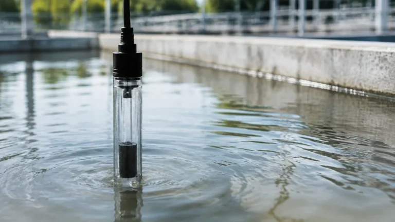
Calorimetric Flow Switch
Calorimetric Flow Switch
In the landscape of industrial automation and process control, monitoring the movement of fluids within a piping system is critical for both safety and efficiency. The calorimetric flow switch, also known as a thermal dispersion flow switch, represents a robust, solid-state solution for detecting flow velocity in liquids and gases. Unlike mechanical flow switches that rely on paddles or pistons, the calorimetric variant utilizes thermal principles to determine if a medium is moving, making it a preferred choice for applications where maintenance-free operation and high reliability are paramount.
This guide provides a comprehensive technical overview of the calorimetric flow switch, detailing its operational physics, selection criteria, and practical installation requirements for engineering professionals.
Understanding the Calorimetric Measurement Principle
The operation of a calorimetric flow switch is based on the physical law of heat transfer. Specifically, it utilizes the "thermal dispersion" effect, where a flowing medium absorbs heat from a heated source. The rate of heat loss is directly proportional to the flow velocity of the medium.
The Dual-Sensor Configuration
Inside the sensing probe of a calorimetric flow switch, two temperature sensors (typically Resistance Temperature Detectors or RTDs) are positioned.
1. The Reference Sensor: This sensor measures the actual ambient temperature of the medium (liquid or gas). It provides a baseline to ensure that changes in the process temperature do not result in false flow readings.
2. The Active (Heated) Sensor: This sensor is heated to a constant internal temperature or provided with a constant heating power, creating a temperature differential between itself and the reference sensor.
The Physics of Flow Detection
When the medium is stationary (zero flow), the temperature difference between the two sensors is at its maximum. As the medium begins to move, it carries heat away from the active sensor—a process known as convective cooling. The higher the flow velocity, the greater the cooling effect.
Modern electronics within the switch monitor this temperature differential. When the flow velocity reaches a user-defined setpoint (where the temperature difference drops to a specific level), the switch changes its output state (e.g., from normally open to normally closed). Because this method measures the mass flow or velocity directly through thermal exchange, it is highly sensitive even at very low flow rates.
Key Advantages in Industrial Applications
Choosing a calorimetric flow switch over mechanical alternatives offers several distinct engineering advantages:
* No Moving Parts: Because there are no paddles, springs, or rotors to wear out or jam, these switches offer an exceptionally long service life and are resistant to mechanical fatigue.
* Low Pressure Drop: The sensor probe typically has a small profile, resulting in negligible resistance to the flow. This is critical in systems where maintaining hydraulic head is important.
* High Sensitivity: Thermal dispersion is effective at detecting very slow movement, often as low as 0.01 m/s in water, which is often below the threshold of mechanical switches.
* Versatility: These switches can be used in a wide variety of media, including water, oils, aggressive chemicals, and gases, provided the materials of construction are compatible.
* Integrated Monitoring: Many units provide both a switching output and a visual LED trend display, allowing operators to see the relative flow rate at a glance.
For a broader look at how these sensors integrate into comprehensive process monitoring systems, engineers can visit the Main Page to review product options and application support.
Technical Selection Criteria and Evaluation
Selecting the correct calorimetric flow switch requires an analysis of the process medium and the environmental conditions. The following table outlines standard evaluation parameters for industrial-grade units.
Selection Table: Typical Performance Specifications
| Parameter | Specification Range (Metric) | Imperial Equivalent (Approx.) |
| :— | :— | :— |
| Measuring Range (Water) | 0.01 to 3.0 m/s | 0.03 to 10 ft/s |
| Measuring Range (Oil) | 0.03 to 5.0 m/s | 0.1 to 16 ft/s |
| Measuring Range (Air/Gas) | 2.0 to 30 m/s | 6.5 to 98 ft/s |
| Operating Pressure | Up to 100 bar | Up to 1450 psi |
| Medium Temperature | -20°C to +120°C | -4°F to +248°F |
| Response Time | 1 to 10 seconds | 1 to 10 seconds |
| Wetted Materials | 316L Stainless Steel, Hastelloy, Titanium | – |
| Output Options | PNP, NPN, Relay, 4-20mA | – |
Media Considerations
The thermal conductivity of the medium significantly impacts the switch's performance. For instance, water is an excellent heat conductor, allowing for very precise switching. Oils have lower thermal conductivity, which requires the switch to be calibrated differently. When ordering, it is essential to specify whether the switch is intended for water-based, oil-based, or gaseous media.
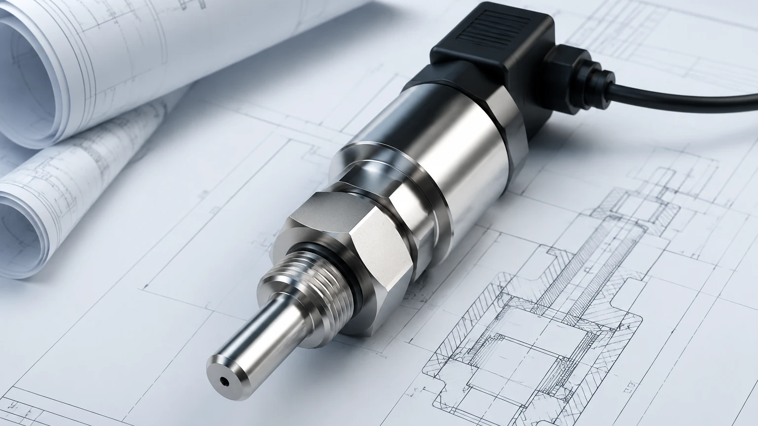
Installation Best Practices for Accuracy
To ensure the calorimetric flow switch operates reliably, specific installation guidelines must be followed. Improper placement is the leading cause of "nuisance switching" or failure to detect flow.
1. Immersion Depth
The sensor tip must be fully immersed in the moving medium. In larger pipes, the probe should ideally reach the center of the pipe, where the flow profile is most stable. In smaller pipes, ensure the tip is not touching the opposite wall, as this can cause heat sink effects that distort the reading.
2. Straight Pipe Runs
To achieve a stable flow profile, the switch should be installed in a straight section of pipe.
* Upstream: Maintain at least 5 times the pipe diameter (5xDN) of straight pipe before the sensor.
* Downstream: Maintain at least 3 times the pipe diameter (3xDN) after the sensor.
Turbulence caused by valves, elbows, or pumps located too close to the sensor will result in erratic switching behavior.
3. Orientation
* Horizontal Pipes: The switch should ideally be installed from the side. Mounting from the top risks the sensor being in an air pocket (if the pipe is not full), while mounting from the bottom risks sediment buildup covering the sensor tip.
* Vertical Pipes: Flow should ideally be in an upward direction to ensure the pipe remains completely full and to prevent air bubbles from gathering at the sensor head.
4. Avoiding Bubbles and Cavitation
Air bubbles in a liquid stream can cause sudden changes in heat transfer, leading to false flow-loss signals. Ensure that the system pressure is sufficient to prevent cavitation and that the sensor is placed away from air-release valves.
Common Operational Risks and Limitations
While highly reliable, the calorimetric flow switch is not suitable for every application. Engineers should be aware of the following limitations:
* Coating and Scaling: If the medium is prone to leaving deposits (such as calcium scaling or heavy grease), a layer of insulation can form on the sensor tip. This reduces the heat transfer efficiency and slows the response time. Regular inspection is required in "dirty" applications.
* Rapid Temperature Fluctuations: Although the reference sensor compensates for ambient temperature changes, extremely rapid spikes in process temperature (e.g., during a steam cleaning cycle) can momentarily confuse the electronics, leading to a temporary false signal.
* Viscosity Changes: Significant changes in fluid viscosity (often caused by temperature swings in heavy oils) can alter the flow profile and heat transfer rate, potentially requiring a setpoint adjustment.
* Response Time: Thermal switches are inherently slower than mechanical switches. While a mechanical paddle reacts almost instantly, a thermal switch may take several seconds to register a change in flow as the sensor reaches thermal equilibrium.
Frequently Asked Questions (FAQ)
Q: Can a calorimetric flow switch be used for gas flow?
A: Yes, but the sensitivity and range differ significantly from liquid applications. Because gases are less dense and have lower thermal conductivity than liquids, the switch requires higher heating power and different calibration.
Q: Is it possible to use these switches in hazardous areas?
A: Yes, many manufacturers offer versions with ATEX or IECEx certifications for use in explosive atmospheres. These usually feature encapsulated electronics and intrinsically safe barriers.
Q: How do I calibrate the setpoint?
A: Most modern calorimetric switches feature a "teach-in" button or a potentiometer. To calibrate, you establish the minimum desired flow in the process and then trigger the switch to recognize this as the threshold. Many units use an LED bar graph to show how close the current flow is to the switch point.
Q: What maintenance is required?
A: Under normal conditions with clean media, no maintenance is required. In applications where coating is possible, the probe tip should be cleaned periodically with a soft cloth and a compatible solvent to ensure optimal heat transfer.
Q: Can the switch be damaged by dry-run conditions?
A: No. One of the benefits of the calorimetric principle is that the sensor is designed to operate in air (zero flow). In fact, these switches are frequently used specifically as dry-run protection for pumps.
By understanding the thermal dynamics and following strict installation protocols, the calorimetric flow switch serves as an essential component in modern industrial fluid management, providing a level of reliability that mechanical equivalents often cannot match.