Hauser Houston
Hauser Houston
In the industrial landscape of the Texas Gulf Coast, precision in process control is not merely a preference but a regulatory and operational necessity. When engineers and procurement specialists search for "hauser houston," they are typically navigating the complex ecosystem of process automation and instrumentation support centered in the energy capital of the world. Houston serves as a global hub for the oil, gas, and petrochemical industries, where the demand for reliable level measurement technology—ranging from radar level meters to magnetic level gauges—is exceptionally high.
Selecting the right level measurement solution requires a deep understanding of physics, fluid dynamics, and environmental constraints. This guide provides a technical overview of the primary level measurement technologies used in industrial applications, selection criteria for harsh environments, and the practical considerations necessary for successful deployment in the field.
Fundamental Principles of Level Measurement
Before selecting a specific instrument or engaging with local service providers in the Houston area, it is essential to understand the measurement principles that govern different technologies. Industrial level measurement is generally divided into two categories: continuous level measurement and point level detection.
1. Radar Level Measurement (Time-of-Flight)
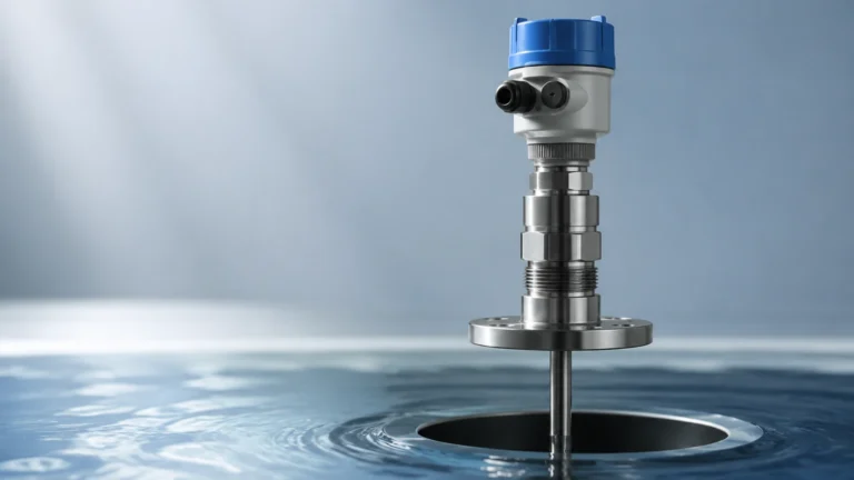
Radar level meters operate on the Time-of-Flight (ToF) principle. The sensor emits a high-frequency electromagnetic wave (typically in the GHz range) toward the surface of the medium. The wave is reflected back to the sensor, and the distance is calculated based on the time interval between emission and reception.
* Non-Contact Radar: These devices emit signals through the air. They are ideal for corrosive media or applications where hygiene is paramount, as the sensor does not touch the liquid. High-frequency 80 GHz radar is increasingly favored in Houston’s refining sector due to its narrow beam angle, which avoids internal tank obstructions.
* Guided Wave Radar (GWR): This technology uses a probe (rod or cable) to guide the electromagnetic pulse. GWR is highly effective in low-dielectric liquids and applications with heavy foam or turbulence, as the probe ensures the signal reaches the surface and returns with minimal loss.
2. Ultrasonic Level Sensors
Ultrasonic sensors function similarly to radar but use sound waves instead of electromagnetic waves. The transducer emits an ultrasonic pulse that reflects off the surface of the material. Because sound speed is influenced by air temperature, these sensors usually include integrated temperature compensation.
Ultrasonic technology is widely used in water treatment and open-channel flow measurement. However, it is limited in vacuum conditions (where sound cannot travel) and in high-pressure environments where the density of the gas phase significantly alters sound velocity.
3. Hydrostatic Level Measurement
Hydrostatic transmitters measure the pressure exerted by a liquid column at a specific point. The relationship is defined by the formula:
P = ρ × g × h
*Where:*
* P = Hydrostatic pressure
* ρ (rho) = Density of the liquid
* g = Gravitational acceleration
* h = Height of the liquid column
This method is highly reliable for vented tanks. In pressurized vessels, a differential pressure (DP) transmitter is required to subtract the top-side gas pressure from the total pressure at the bottom.
4. Magnetic Level Gauges
Magnetic level gauges utilize a float containing a permanent magnet that moves within a bypass chamber connected to the process vessel. As the float rises and falls with the liquid level, the magnet flips colored flaps or activates a reed chain transmitter on the outside of the chamber. This provides both a local visual indication and an electronic signal for the control room without the risk of glass breakage associated with traditional sight glasses.
Industrial Selection Criteria
When evaluating instrumentation for a project, engineers must match the technology to the specific process conditions. The following table provides a comparison of common technologies used in industrial automation.
Technology Selection Matrix
| Technology | Typical Accuracy | Max Temperature | Max Pressure | Media Characteristics |
| :— | :— | :— | :— | :— |
| 80GHz Radar | ±1 mm | Up to 450°C (842°F) | Up to 160 bar | Liquids, solids, corrosive media |
| Guided Wave Radar | ±2 mm | Up to 400°C (752°F) | Up to 400 bar | Low dielectric liquids, foam |
| Ultrasonic | ±0.25% of range | Up to 80°C (176°F) | Up to 3 bar | Water, wastewater, simple liquids |
| Hydrostatic | ±0.1% of span | Up to 100°C (212°F) | Dependent on sensor | Constant density liquids |
| Magnetic Gauge | ±5 mm | Up to 400°C (752°F) | Up to 250 bar | Clean liquids, interface levels |
Installation Considerations and Best Practices
Even the most advanced instrument will fail to provide accurate data if installed incorrectly. In the heavy industrial environments typical of the Houston ship channel, the following factors must be addressed during the engineering phase:
Nozzle Geometry and Dead Zones
For radar and ultrasonic sensors, the nozzle height and diameter are critical. If a nozzle is too narrow or too long, the signal may reflect off the nozzle wall before reaching the medium, creating a "ringing" effect that masks the true level. Every sensor has a "dead zone" (or blocking distance) near the transducer face where measurements are not possible. The instrument must be mounted high enough to ensure the maximum liquid level never enters this zone.
Internal Obstructions
Agitators, heating coils, and ladders can create false echoes. While modern software can "map out" these obstructions, it is best practice to install the sensor in a location with a clear line of sight to the liquid surface. For non-contact radar, the beam should generally be positioned at 1/6th of the tank diameter away from the wall to avoid interference from wall reflections while staying clear of the center-tank vortex.
Environmental Protection
In Houston’s humid and saline environment, housing materials matter. Stainless steel (316L) housings are preferred over aluminum for longevity. Furthermore, lightning protection and surge suppression are essential for outdoor tank farms to prevent electronics failure during the region’s frequent electrical storms.
Common Risks in Level Measurement
1. Vapor and Condensation: In high-temperature hydrocarbon storage, heavy vapors can attenuate radar signals, while condensation on an ultrasonic transducer face can cause a "loss of echo." Selecting a radar unit with a PTFE dropper antenna or a parabolic antenna can mitigate these risks.
2. Density Fluctuations: Hydrostatic level measurement assumes a constant liquid density. If the process involves temperature swings that change the density, the level reading will drift. In such cases, a guided wave radar or a system with integrated density compensation is required.
3. Foam Interference: Thick, dense foam can absorb radar and ultrasonic signals. If foam is a permanent process feature, Guided Wave Radar (GWR) is usually the most robust choice because the probe focuses the energy, allowing it to penetrate the foam layer and detect the true liquid surface.
Maintenance and Calibration in the Field
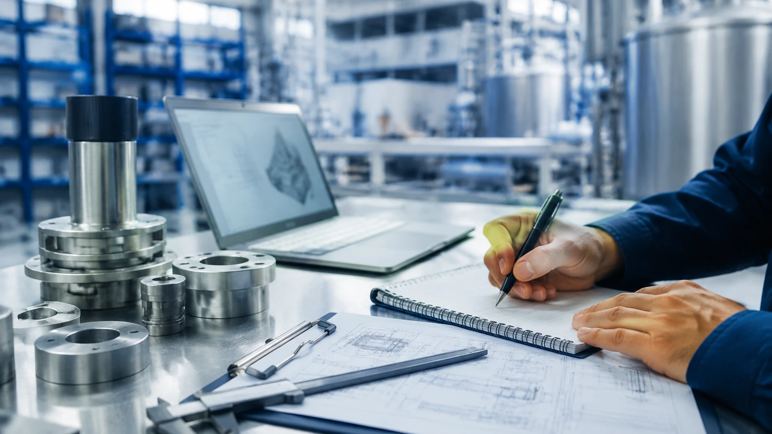
To maintain the integrity of a process, regular verification is required. In the Houston industrial sector, many facilities follow a scheduled calibration cycle.
* In-situ Verification: Many modern digital transmitters support onboard diagnostics that can verify the health of the electronics and the integrity of the signal without removing the device from the process.
* Bench Calibration: For critical custody transfer or safety-instrumented systems (SIS), instruments are often removed and calibrated against a traceable standard.
* Magnetic Gauge Buoyancy Checks: For magnetic gauges, it is vital to periodically check for build-up inside the chamber which could cause the float to stick. Flushing the bypass chamber is a standard maintenance task in refineries.
Frequently Asked Questions (FAQ)
Q: Can radar be used in a vacuum?
A: Yes. Unlike ultrasonic waves, which require a medium (air/gas) to travel, radar electromagnetic waves travel through a vacuum without any degradation.
Q: How does the dielectric constant (DC) affect measurement?
A: For radar, the DC determines how much energy is reflected. Water has a high DC (~80) and is easy to measure. Hydrocarbons have low DCs (1.9 to 4.0), requiring more sensitive electronics or guided wave technology to ensure a reliable return signal.
Q: What is the benefit of a bypass chamber?
A: A bypass chamber (or stilling well) isolates the measurement from turbulence and foam inside the main vessel, providing a stable surface for the instrument to track.
Taking the Next Step in Process Automation
Selecting a level measurement partner involves more than just buying a sensor; it requires a technical alignment between the process requirements and the instrument’s capabilities. Whether you are upgrading a legacy tank farm or designing a new chemical processing unit, confirming the chemical compatibility of wetted parts, the required hazardous area certifications (ATEX/IECEx/FM), and the communication protocol (HART, Modbus, Profibus) is essential before procurement.
For those seeking reliable, accurate, and cost-effective level measurement solutions, exploring a comprehensive range of industrial instruments is the first step toward operational excellence. To learn more about specific technologies and how they apply to your unique process challenges, you can Review product options and application support at our Main Page. Ensuring you have the right data today prevents the costly downtime of tomorrow.