Radar Level Transmitter Uses
Radar Level Transmitter Uses: A Comprehensive Engineering Guide to Industrial Application
In the landscape of industrial process control, the ability to accurately monitor material levels is fundamental to operational safety, inventory management, and process efficiency. Among the various technologies available, radar-based measurement has emerged as a premier solution due to its versatility and reliability in challenging environments. This guide explores the diverse radar level transmitter uses, the underlying physics of the technology, and the critical factors engineers must consider when selecting and installing these instruments.
Understanding the Measurement Principles
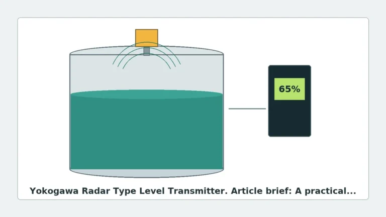
Before detailing specific applications, it is essential to understand how radar level measurement functions. Unlike ultrasonic sensors that rely on sound waves (mechanical energy), Radar Level Meters utilize electromagnetic waves, typically in the microwave spectrum. These waves travel at the speed of light and are reflected by the surface of the medium being measured.
There are two primary methods of radar measurement used in industrial instrumentation:
1. Pulse Radar (Time-of-Flight)
Pulse radar transmitters emit a short microwave signal toward the product surface. The instrument measures the time it takes for the pulse to travel to the surface and return to the sensor. Since the speed of light is constant, the distance is calculated as:
*Distance = (Speed of Light × Time-of-Flight) / 2*
2. Frequency Modulated Continuous Wave (FMCW)
FMCW radar transmits a continuous signal with a constantly changing frequency. The frequency of the reflected signal is compared to the frequency of the signal being transmitted at that moment. The difference between these frequencies is directly proportional to the distance. FMCW is generally preferred for high-precision industrial applications because it offers a better signal-to-noise ratio and superior accuracy in complex environments.
Primary Radar Level Transmitter Uses across Industries
The versatility of radar technology allows it to be used in a wide array of industrial scenarios. The following are the most common radar level transmitter uses identified in modern process engineering:
Chemical and Petrochemical Storage
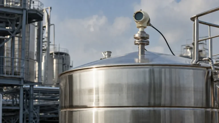
In the chemical industry, storage tanks often contain aggressive, corrosive, or volatile substances. Because non-contact radar sensors do not touch the medium, they are immune to chemical attack. They are frequently used for measuring acids, bases, and solvents. In the petrochemical sector, radar is the standard for large-scale crude oil storage and refined product tanks where high precision (often within ±1 mm) is required for custody transfer.
Water and Wastewater Management
Radar level transmitters are ideal for water treatment plants, particularly in open-channel flow measurement, wet wells, and chemical dosing tanks. Unlike ultrasonic sensors, radar is not affected by air temperature fluctuations, wind, or surface vapors, making it highly reliable for outdoor installations at reservoirs or dam sites.
Solids and Bulk Material Handling
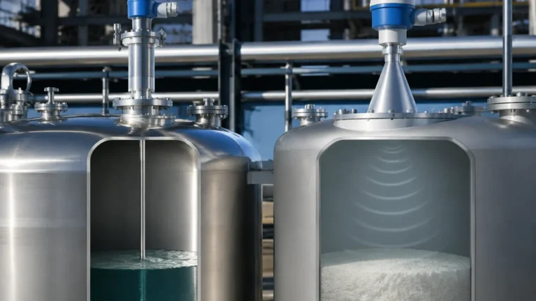
Measuring the level of solids presents unique challenges, such as dust generation, uneven surfaces (cones and craters), and low dielectric constants. High-frequency radar (such as 80GHz) is specifically used in silos containing cement, plastic pellets, grain, or ores. The narrow beam angle of high-frequency radar helps avoid interference from internal silo structures and wall buildup.
High-Temperature and High-Pressure Reactors
In many industrial processes, such as plastic polymerization or steam drum level control, temperatures can exceed 400°C (752°F) and pressures can reach over 100 bar (1450 psi). Specialized radar transmitters equipped with ceramic seals and cooling fins are used to maintain accuracy under these extreme conditions where hydrostatic or float-based systems might fail.
Selection Criteria: Choosing the Right Radar Technology
Selecting the correct instrument involves more than just identifying the medium. Engineers must evaluate the dielectric constant ($ε_r$) of the material, the tank geometry, and the presence of internal obstructions.
| Feature | 26GHz Radar | 80GHz Radar | Guided Wave Radar (GWR) |
| :— | :— | :— | :— |
| Measurement Type | Non-contact | Non-contact | Contact (Probe-based) |
| Beam Angle | Moderate (approx. 10°-15°) | Narrow (approx. 3°-4°) | Focused along probe |
| Dust/Vapor Resistance | Good | Excellent | Excellent |
| Small Tank Suitability | Fair | Excellent | Excellent |
| Low Dielectric (ε_r < 1.4)| Challenging | Good | Best |
| Typical Accuracy | ±3 mm to ±5 mm | ±1 mm | ±2 mm |
The Importance of Frequency
One of the most significant advancements in radar level transmitter uses is the shift toward higher frequencies. An 80GHz transmitter provides a much narrower beam than a 6GHz or 26GHz unit. This allows the signal to avoid internal obstacles like agitators, heating coils, or ladders, which are common in industrial mixing tanks.
Installation Considerations and Practical Constraints
To ensure the radar level transmitter performs to its specifications, several installation rules must be followed:
1. Nozzle Height and Diameter: The mounting nozzle should be as short as possible. If the nozzle is too long or narrow, it can create "ringing" or false echoes that interfere with the signal near the top of the tank (the "dead zone").
2. Obstruction Avoidance: The radar beam should have a clear path to the material surface. It should not be installed directly above an inflow stream or near internal struts.
3. Positioning: Generally, the sensor should be mounted at 1/4 to 1/3 of the tank diameter from the wall. Mounting too close to the wall can cause interference, while mounting in the exact center can lead to multiple reflections in domed-roof tanks.
4. Dead Zone (Blocking Distance): Every radar has a minimum distance it can measure near the sensor face (typically 50mm to 300mm). The process high-level alarm should be set below this zone to prevent measurement loss.

Limitations and Application Risks
While radar is highly robust, it is not a universal solution for every problem. Engineers should be aware of the following limitations:
* Dielectric Constant ($ε_r$): The strength of the reflected signal depends on the dielectric constant of the medium. Non-polar liquids like oils and hydrocarbons have low $ε_r$ values (around 1.9 to 2.1), resulting in weaker reflections. Materials with $ε_r < 1.4$ may require Guided Wave Radar or specialized high-sensitivity non-contact units.
* Heavy Foam: Dense, thick foam can absorb the radar signal entirely, preventing a return echo. While some radar units can track the surface through light foam, heavy foam often requires a Guided Wave Radar or a different technology like a magnetic level gauge.
* Turbulence: Extreme surface agitation can scatter the radar signal. In these cases, using a stilling well or a bypass pipe is recommended to provide a calm surface for measurement.
International Buyer’s Checklist
When procuring radar level transmitters for international projects, buyers should confirm the following technical details with the manufacturer to ensure site compatibility:
1. Process Connection Standards: Ensure the flange or thread standards (ANSI, DIN, JIS) match the local piping specifications.
2. Hazardous Area Certifications: Verify if the site requires ATEX, IECEx, or UL/CSA certifications for explosive atmospheres.
3. Output Protocols: Most modern units offer 4-20mA with HART, but some applications may require Modbus RTU, Foundation Fieldbus, or Profibus.
4. Material Compatibility: Confirm that the wetted parts (e.g., PTFE, 316L Stainless Steel, Hastelloy) are compatible with the process medium.
Frequently Asked Questions (FAQ)
Q: Can radar measure level through a plastic tank wall?
A: Yes. Since plastic is non-conductive and has a low dielectric constant, microwaves can pass through the top of a plastic or fiberglass tank, allowing for measurement without cutting a hole in the vessel.
Q: Is radar better than ultrasonic for level measurement?
A: Generally, yes. Radar is not affected by vacuum, pressure, dust, or temperature changes in the vapor space, whereas ultrasonic waves are heavily influenced by the density and temperature of the air.
Q: How do I handle a low dielectric liquid in a tall silo?
A: Guided Wave Radar is usually the most reliable choice for low dielectric materials in tall vessels because the probe guides the signal, preventing it from dissipating over long distances.
Q: Does the color of the liquid affect the radar?
A: No. Unlike laser-based sensors, radar is unaffected by the optical properties of the medium, such as color, transparency, or ambient light.
Conclusion
The diverse range of radar level transmitter uses makes this technology a cornerstone of modern industrial automation. By understanding the differences between pulse and FMCW methods, and by carefully matching the frequency and mounting style to the specific constraints of the application, engineers can achieve highly accurate and maintenance-free level monitoring. Whether dealing with corrosive chemicals, dusty solids, or high-pressure steam, radar provides a scalable and reliable solution for the most demanding process environments.