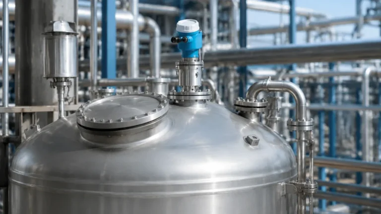
Radar Level Transmitter Unit
Radar Level Transmitter Unit: A Comprehensive Engineering Guide to Selection and Application
In the landscape of industrial process automation, the ability to accurately monitor liquid and solid levels is fundamental to operational safety, inventory management, and process efficiency. Among the various technologies available, the radar level transmitter unit has emerged as a premier solution for challenging environments. Unlike ultrasonic sensors that rely on sound waves or hydrostatic sensors that depend on physical pressure, radar technology utilizes electromagnetic waves, making it largely immune to changes in air temperature, pressure, and vapor composition.
This guide provides a detailed technical overview of radar level measurement, exploring the underlying physics, selection criteria, and installation best practices essential for instrumentation engineers and procurement specialists.
Understanding the Measurement Principles
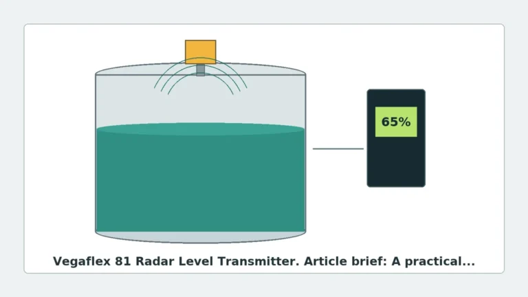
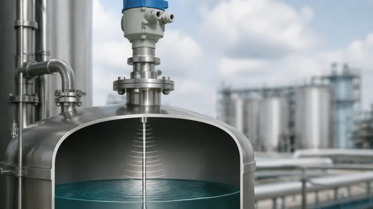
A radar level transmitter unit operates by emitting high-frequency electromagnetic waves (typically in the microwave spectrum) toward the medium being measured. These waves reflect off the surface of the material and return to the sensor's antenna. The instrument then calculates the distance based on the properties of the returned signal. There are two primary methods used in industrial radar measurement: Pulse Radar and Frequency Modulated Continuous Wave (FMCW).
1. Pulse Radar (Time of Flight)
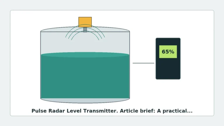
Pulse radar instruments emit a short microwave pulse and measure the time it takes for the pulse to travel to the product surface and back to the antenna. Since the speed of light is constant, the distance is calculated using the formula:
*Distance = (Speed of Light × Travel Time) / 2*.
This method is known for its energy efficiency and is often used in battery-powered or loop-powered applications.
2. Frequency Modulated Continuous Wave (FMCW)
FMCW radar transmits a continuous signal with a constantly changing frequency (a frequency sweep). When the reflected signal is received, it is compared with the signal being transmitted at that moment. The frequency difference between the transmitted and received signals is directly proportional to the distance. FMCW is generally considered more accurate than pulse radar and offers a better signal-to-noise ratio, making it ideal for complex tanks with internal obstructions or turbulent surfaces.
Key Components of a Radar Level Transmitter Unit
To specify the correct equipment, it is important to understand the modular nature of a modern Radar Level Meters system. A standard unit typically consists of:
* The Electronic Module: Processes the signal, performs false-echo suppression, and converts the measurement into a 4-20mA, HART, Modbus, or Profibus output.
* The Antenna: The interface that launches the radar waves. Common types include horn antennas (for high gain), rod antennas (for corrosive liquids), and parabolic antennas (for long-range solids measurement).
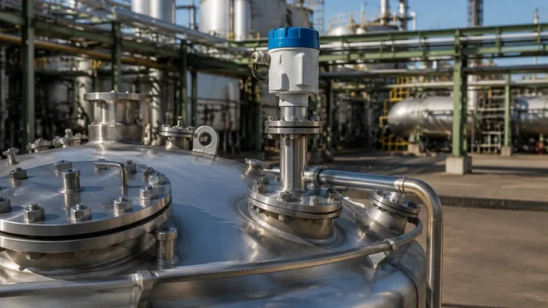
* The Process Connection: The mechanical interface (flange or thread) that secures the unit to the vessel.
Selection Criteria: Choosing the Right Frequency
The frequency of a radar level transmitter unit significantly impacts its performance. Industrial radars generally fall into three frequency bands:
| Frequency Band | Typical Range | Best Use Cases | Advantages | Limitations |
| :— | :— | :— | :— | :— |
| C-Band (Low) | 6 GHz – 10 GHz | Heavy steam, foam, or turbulent surfaces. | Penetrates vapor and light foam effectively. | Large beam angle (requires large tanks/nozzles). |
| K-Band (Mid) | 24 GHz – 26 GHz | Standard industrial tanks, oils, and chemicals. | Good balance of precision and antenna size. | Can be affected by heavy condensation or thick foam. |
| W-Band (High) | 76 GHz – 81 GHz | Small vessels, narrow nozzles, and solids. | Extremely narrow beam; very high precision (±1mm). | Sensitive to heavy buildup on the antenna. |
The Role of the Dielectric Constant (εr)
Radar measurement relies on the difference in the dielectric constant between the air (εr ≈ 1) and the process medium. Materials with a high dielectric constant, such as water (εr ≈ 80), reflect signals very strongly. Hydrocarbons and solvents often have low dielectric constants (εr < 2), which results in weaker reflections. When selecting a radar level transmitter unit for low-dielectric fluids, engineers must choose high-sensitivity electronics or consider Guided Wave Radar (GWR).
Guided Wave Radar (GWR) vs. Non-Contact Radar
While non-contact radar is popular for its maintenance-free nature, Guided Wave Radar is a specific type of radar level transmitter unit that uses a physical probe (cable or rod) to guide the microwave signal.
* Non-Contact Radar: Ideal for corrosive or hygienic applications where the sensor should not touch the medium. It is easier to install on existing tanks without emptying them.
* Guided Wave Radar: Superior for low-dielectric liquids, interface measurement (e.g., oil over water), and narrow bypass chambers. It is less affected by foam or extreme turbulence because the signal is concentrated along the probe.
Practical Installation Considerations
Even the most advanced radar level transmitter unit will fail to provide accurate data if installed incorrectly. Follow these engineering guidelines to ensure signal integrity:
1. Avoid the Center: Never mount a radar unit in the exact center of a circular tank. This can cause multiple reflections to converge, creating a "false peak" that mimics a high level.
2. Nozzle Geometry: The nozzle height should be kept as short as possible. If the nozzle is too long or narrow, the radar signal may reflect off the nozzle walls before even entering the tank. For 80 GHz units, this is less of a concern due to the narrow beam.
3. Obstruction Clearance: Ensure the "beam spread" (the cone-shaped path of the signal) does not intersect with ladders, agitators, or heating coils. If obstructions are unavoidable, use the instrument’s "False Echo Mapping" software to tell the transmitter to ignore those specific static reflections.
4. Inflow Streams: Do not install the sensor directly above the point where product enters the tank. The falling stream will scatter the signal and cause erratic readings.
5. Metric Alignment: Most international projects utilize metric standards (e.g., DN80 flanges). Ensure the process connection of the radar level transmitter unit matches the local piping standards (ANSI vs. DIN) to avoid costly field adaptations.

Limitations and Application Risks
While highly versatile, radar technology is not a universal solution. Engineers should be aware of the following risks:
* Heavy Foam: While C-band radar can penetrate some foam, extremely dense, thick foam (like shaving cream) can absorb the radar signal entirely, leading to a "Loss of Echo" (LOE) error.
* Vacuum and High Pressure: While the radar signal itself is unaffected by vacuum, the mechanical seals of the transmitter must be rated for the specific pressure and temperature of the vessel.
* Crystallization and Buildup: If the process medium tends to crystallize or coat the antenna, the signal strength will degrade. In these cases, units with PTFE-enclosed antennas or air-purging systems are recommended.
Maintenance and Troubleshooting
Radar level transmitter units are generally low-maintenance because they have no moving parts. However, periodic verification is recommended:
* Signal Strength Monitoring: Check the "Echo Curve" via the device display or a connected laptop. A diminishing signal-to-noise ratio usually indicates buildup on the antenna or a failing electronic module.
* Calibration Verification: Perform a manual dip-tape measurement and compare it with the transmitter reading. Ensure the "Zero Point" (tank bottom) and "Full Point" are correctly mapped in the software.
* Environmental Protection: Ensure the housing cover is tightened and cable glands are sealed to prevent moisture ingress, which is the leading cause of electronic failure in outdoor installations.
Frequently Asked Questions (FAQ)
Q: Can a radar level transmitter unit measure through a plastic tank wall?
A: Yes. Non-metallic materials like plastic, glass, or fiberglass are transparent to microwaves. If the tank is made of these materials, the sensor can often be mounted outside the tank, looking through the top, provided the material is not too thick or reinforced with metal fibers.
Q: What is the difference between 2-wire and 4-wire radar units?
A: A 2-wire (loop-powered) unit uses the same pair of wires for both power and the 4-20mA signal, simplifying wiring. A 4-wire unit has separate power and signal wires, allowing for higher power consumption, which is often needed for high-speed solids measurement or heated displays.
Q: How does dust affect radar measurement?
A: Unlike ultrasonic sensors, radar is largely unaffected by dust. However, in extremely dusty environments (like flour or cement silos), high-frequency 80 GHz Radar Level Meters are preferred because their narrow beam can better navigate through dust clouds and avoid reflections from the silo walls.
Conclusion
Selecting the appropriate radar level transmitter unit requires a thorough understanding of the process medium, vessel geometry, and environmental conditions. By prioritizing the correct frequency and adhering to strict installation standards, industrial facilities can achieve highly reliable level monitoring. Whether dealing with corrosive chemicals, volatile hydrocarbons, or bulk solids, radar technology remains the gold standard for non-contact level measurement in the modern B2B industrial sector.