Rotameter Calibration
Rotameter Calibration
In the landscape of industrial process control, the accuracy of flow measurement is as critical as the precision of level sensing. Rotameters, also known as variable area (VA) flow meters, are among the most widely used instruments for measuring the flow rate of liquids and gases due to their simplicity, reliability, and cost-effectiveness. However, the inherent mechanical nature of these devices means that rotameter calibration is essential to ensure that the visual or electronic output reflects the true flow conditions within a pipe. For engineers and plant managers, understanding the nuances of calibration is the first step toward maintaining system integrity and operational efficiency.
Measurement Principles of Variable Area Flow Meters
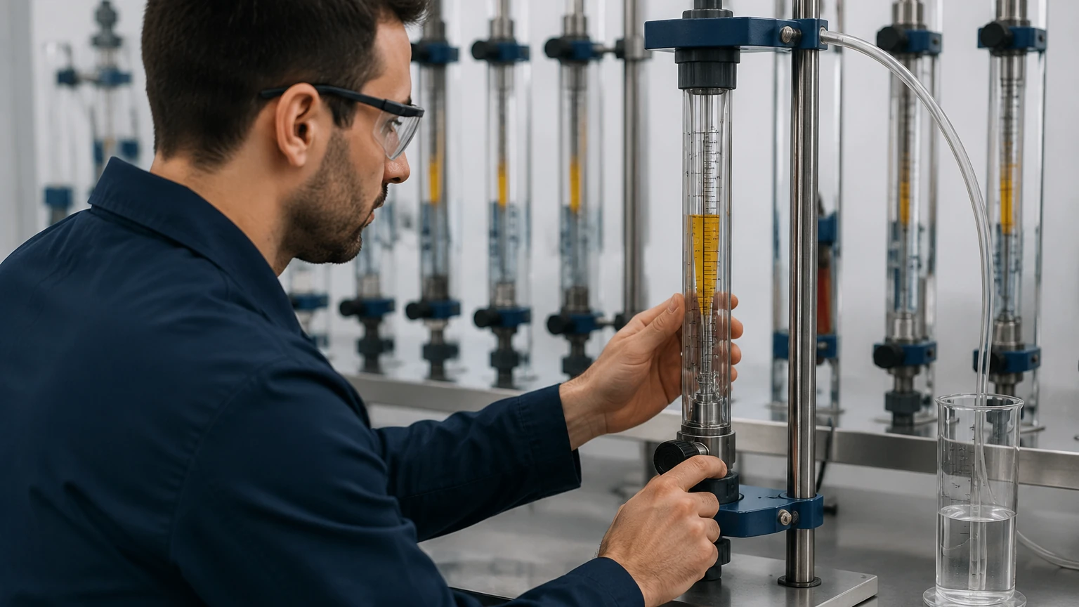
Before addressing the specifics of calibration, it is necessary to understand the physics governing a rotameter. A rotameter consists of a tapered tube, typically made of glass, metal, or plastic, and a float that moves freely inside the tube.
As fluid enters the bottom of the tapered tube, it forces the float upward. The flow rate is determined by the equilibrium reached between several competing forces:
1. Gravity: The downward force exerted by the mass of the float.
2. Buoyancy: The upward force exerted by the displaced fluid.
3. Drag (Pressure): The upward force exerted by the kinetic energy of the moving fluid.
As the float rises, the annular area (the space between the float and the tube wall) increases. The float reaches a stable position when the upward forces of drag and buoyancy exactly balance the downward force of gravity. Because the tube is tapered, each height corresponds to a specific cross-sectional area, and therefore a specific flow rate. Because this balance is dependent on the density and viscosity of the fluid, any change in fluid properties or environmental conditions necessitates a review of the instrument's calibration.
The Critical Role of Rotameter Calibration in Industry
Rotameter calibration is the process of verifying and adjusting the instrument to ensure its readings match a known reference standard. Unlike some digital sensors that can be programmed with fluid constants, a rotameter’s scale is often physically etched or printed based on a specific set of calibration conditions—usually water at 20°C (68°F) or air at standard atmospheric pressure.
In B2B industrial environments, such as chemical processing, water treatment, and oil and gas, calibration serves several purposes:
* Accuracy Verification: Factory calibrations can shift over time due to mechanical wear, corrosion of the float, or buildup of scale inside the tube.
* Fluid Specificity: If a rotameter calibrated for water is used to measure an oil with a different density and viscosity, the reading will be fundamentally incorrect.
* Regulatory Compliance: Many industries require documented calibration certificates to meet ISO standards or safety regulations.
* Process Optimization: Precise flow control prevents chemical over-dosing and ensures that cooling systems operate within their designed thermal limits.
For facilities integrating flow systems with advanced level measurement, reviewing the Main Page of specialized manufacturers like Welk can provide insights into how these instruments work in tandem with radar and ultrasonic level sensors to provide a complete picture of fluid dynamics.
Primary Methods for Rotameter Calibration
There are three primary methods used to calibrate or verify the accuracy of a rotameter. The choice of method depends on the required precision, the fluid type, and whether the calibration is performed in a laboratory or on-site.
1. Master Meter Method
This is the most common method for field verification. A "Master Meter"—a high-accuracy flow meter that has been recently certified in a primary lab—is connected in series with the rotameter under test. The same fluid passes through both meters, and the readings are compared across various points (typically 10%, 30%, 50%, 70%, and 90% of the full scale).
2. Gravimetric (Weight-Time) Method
Considered the most accurate method, the gravimetric approach involves weighing the amount of liquid that passes through the rotameter over a specific period. By using a high-precision scale and a calibrated stopwatch, the mass flow rate is calculated. This is then converted to a volume flow rate using the fluid's density. This method is primarily used in calibration laboratories for primary standards.
3. Volumetric Method
Similar to the gravimetric method, this involves collecting the fluid in a calibrated vessel (a "prover") over a set time. For gas rotameters, a "bell prover" or a piston displacement system is often used to measure the exact volume of gas displaced. This is highly effective for low-flow gas applications.
Step-by-Step Procedure for Field and Lab Calibration
When performing a rotameter calibration, follow these standardized steps to ensure repeatable results:
1. Inspection: Check the tapered tube for cracks, erosion, or chemical buildup. Ensure the float moves freely and that the "metering edge" (the part of the float used to read the scale) is sharp and undamaged.
2. Installation Check: Ensure the rotameter is mounted perfectly vertical. Even a few degrees of tilt can increase friction between the float and the tube wall, leading to significant errors.
3. Fluid Stabilization: Run the fluid through the system until the temperature and pressure have stabilized. Air bubbles in a liquid line or moisture in a gas line will invalidate the calibration.
4. Data Collection: Adjust the flow to reach specific points on the rotameter scale. At each point, record the reading from the master meter or the weight/volume collected.
5. Calculate Error: Use the formula: `Percentage Error = [(Indicated Flow – Actual Flow) / Full Scale Flow] x 100`.
6. Adjustment or Scale Replacement: If the error exceeds the manufacturer's specification (typically ±1% to ±5% FS), the scale may need to be shifted, or a correction factor must be applied to future readings.
Fluid Property Corrections: Density, Viscosity, and Pressure
One of the most common mistakes in industrial flow measurement is ignoring the effect of fluid properties. If the operating conditions differ from the calibration conditions, a correction factor must be applied.
Density Correction
Since the float relies on buoyancy and momentum, a denser fluid will push the float higher than a less dense fluid at the same flow rate.
* Liquid Correction: $Q_{actual} = Q_{indicated} \times \sqrt{\frac{(\rho_f – \rho_a) \times \rho_c}{(\rho_f – \rho_c) \times \rho_a}}$
*(Where $\rho_f$ is float density, $\rho_c$ is calibration fluid density, and $\rho_a$ is actual fluid density)*.
Gas Pressure and Temperature Correction
Gases are compressible, meaning their density changes drastically with pressure and temperature. If a gas rotameter is calibrated at 1.01 bar (14.7 psi) but used at 5 bar (72.5 psi), the reading will be significantly lower than the actual flow unless a square-root correction is applied based on the absolute pressure ratio.
Selection and Installation Best Practices
Choosing the right rotameter is as important as the calibration itself. The following table compares common rotameter materials used in industrial B2B applications:
| Feature | Glass Tube Rotameter | Metal Tube Rotameter | Plastic (Acrylic/PVC) |
| :— | :— | :— | :— |
| Typical Accuracy | ±1.0% to ±2.0% FS | ±1.0% to ±1.5% FS | ±2.0% to ±5.0% FS |
| Max Pressure | Up to 20 bar (290 psi) | Up to 400+ bar (5800 psi) | Up to 10 bar (145 psi) |
| Max Temperature | 120°C (248°F) | 400°C (752°F) | 60°C (140°F) |
| Visibility | Direct visual float | Magnetic indicator/Transmitter | Direct visual float |
| Corrosion Resistance | High (except HF/Alkalis) | High (316SS/Hastelloy) | High (for specific acids) |
Installation Considerations:
* Straight Pipe Runs: While rotameters are less sensitive to turbulence than orifice plates, it is still recommended to have 5 to 10 pipe diameters of straight run upstream to ensure a stable flow profile.
* Pulsation Dampening: If the rotameter is installed downstream of a reciprocating pump, the float may oscillate violently. Use a pulsation dampener to protect the instrument and ensure a readable float position.
* Valving: Always place the flow control valve downstream for liquid applications to keep the tube full, and upstream for gas applications if the meter is calibrated for atmospheric pressure.
Limitations and Common Risks
While rotameters are versatile, they have inherent limitations that can impact the success of a rotameter calibration program:
* Parallax Error: In glass or plastic tubes, the operator must read the float at eye level. Reading from an angle can introduce a 1-2% error.
* Opaque Fluids: In glass tubes, if the fluid is too dark, the float cannot be seen. In these cases, a metal tube rotameter with a magnetic follower is required.
* Viscosity Limits: If the fluid is too viscous, the drag force becomes dominated by viscous shear rather than kinetic energy, making the meter highly sensitive to temperature-induced viscosity changes.
* Float Damage: Even microscopic pitting on a float can change its mass and aerodynamic profile, rendering the original calibration void.
Frequently Asked Questions (FAQs)
Q: How often should a rotameter be calibrated?
A: For most industrial applications, an annual calibration is standard. However, if the fluid is corrosive or contains particulates that could erode the float or tube, semi-annual checks are recommended.
Q: Can I calibrate a rotameter myself?
A: Basic verification can be done on-site using the Master Meter or Volumetric method. However, for certified accuracy required for custody transfer or high-stakes chemical dosing, the instrument should be sent to a lab with ISO/IEC 17025 accreditation.
Q: Why is my rotameter reading high after I switched from water to a light oil?
A: Light oils are generally less dense than water but more viscous. While the lower density would typically make the float sit lower, the increased viscous drag often pulls the float higher, leading to an over-reading. A specific rotameter calibration for the new fluid's viscosity is required.
Q: Do rotameters require power?
A: Standard rotameters are purely mechanical and require no power. However, many modern metal tube rotameters include electronic transmitters (4-20mA or HART) for integration into PLC systems, which do require a power supply.
Conclusion
Rotameter calibration is a fundamental requirement for any facility prioritizing precision in fluid handling. By understanding the mechanical principles of variable area measurement and accounting for the specific properties of the process fluid, engineers can ensure long-term reliability. Whether you are using simple glass tubes for laboratory water or rugged metal tube meters for high-pressure steam, regular calibration prevents costly process errors and equipment downtime.
For comprehensive solutions in industrial measurement, including advanced level transmitters and switches that work alongside your flow infrastructure, visit the Welk Main Page to explore professional-grade instrumentation tailored to your application's specific needs.