How Coriolis Flow Meter Works
How Coriolis Flow Meter Works
In the landscape of industrial process control, the ability to measure mass flow directly, rather than inferring it from volume, represents a significant leap in accuracy and reliability. The Coriolis flow meter is widely regarded as the "gold standard" for flow measurement due to its high precision and multivariable output. Understanding how Coriolis flow meter works is essential for engineers and plant managers who require exacting standards in applications ranging from chemical dosing to custody transfer in the oil and gas sector.
As a professional manufacturer of industrial measurement instruments, Welk provides high-performance solutions designed for complex environments. This guide details the physical principles, mechanical construction, and practical application criteria for Coriolis technology to assist in technical selection and system design.
The Fundamental Principle of Coriolis Measurement
To understand how Coriolis flow meter works, one must first look at the Coriolis effect, a phenomenon of physics first described by Gaspard-Gustave de Coriolis in 1835. The effect describes the inertial force acting on an object that is in motion within a rotating frame of reference.
The Vibrating Tube Mechanism
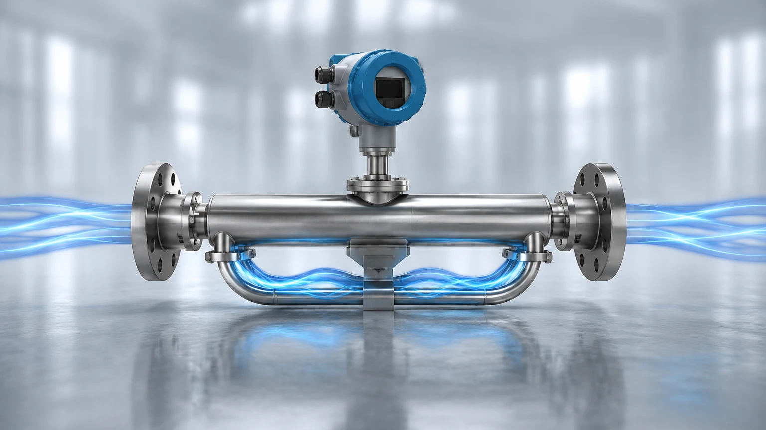
In a Coriolis flow meter, the "rotating frame" is replaced by a vibrating measuring tube. The meter consists of one or more tubes (often U-shaped or straight) that are intentionally vibrated at their resonant frequency by an electromagnetic drive coil. This vibration is typically a small, high-frequency oscillation.
When there is no fluid flowing through the tube, the tube vibrates uniformly. Sensors (pick-offs) located at the inlet and outlet sides of the tube detect this oscillation as a synchronized sine wave. Because there is no mass moving through the vibrating system, the sine waves from the inlet and outlet sensors are in phase.
The Introduction of Mass Flow
When a fluid (liquid or gas) begins to flow through the vibrating tube, the mass of the fluid is subjected to the Coriolis force. As the fluid moves toward the point of maximum vibration (the bend in a U-shaped tube), it resists being pushed upward and exerts a downward force on the tube. Conversely, as the fluid moves away from the center of vibration toward the outlet, it resists the slowing of its vertical motion and exerts an upward force.
This results in a twisting or "twisting moment" of the measuring tube. The inlet side of the tube lags behind the driving vibration, while the outlet side leads ahead of it. This physical distortion causes a phase shift between the signals generated by the inlet and outlet sensors.
Phase Shift and Mass Flow Calculation
The time difference ($Δt$) between the two sine waves is directly proportional to the mass flow rate ($m$). The relationship can be simplified by the following logic: the greater the mass flow, the greater the Coriolis force, the more the tube twists, and the larger the phase shift recorded by the sensors. Because this measurement is based on mass and inertia, it is independent of fluid properties such as viscosity, conductivity, and flow profile.
Multivariable Measurement Capabilities
One of the primary reasons Coriolis meters are favored in modern industrial automation is their ability to measure more than just mass flow. By analyzing the vibration characteristics of the tube, the meter provides several data points simultaneously.
Density Measurement
The resonant frequency at which the tube vibrates is determined by the mass of the tube itself and the mass of the fluid inside it. If the volume of the tube is constant, the resonant frequency changes based on the density of the fluid. A denser fluid increases the total mass of the system, causing the tube to vibrate at a lower frequency. By measuring this frequency, the meter can calculate the fluid's density in real-time ($kg/m³$).
Temperature Measurement
Since the elasticity of the measuring tube changes with temperature, Coriolis meters include an internal temperature sensor (usually a PT100). This sensor is used to compensate for the mechanical changes in the tube material, ensuring accuracy across varying process conditions. This temperature data is also available as a secondary output for the user.
Volumetric Flow Calculation
With the direct measurement of mass flow and density, the meter can mathematically derive the volumetric flow rate ($V = m / ρ$). This allows the instrument to replace multiple sensors in a process loop, simplifying the Main Page of the control system architecture.
Mechanical Design and Tube Geometries
The construction of a Coriolis meter significantly impacts its performance and suitability for specific applications. Most industrial meters utilize one of two primary designs:
1. U-Shaped Tubes: These are the most common and offer the highest sensitivity. The curved shape allows for a greater degree of twist for a given flow rate, making them ideal for low-flow applications. However, they can be larger in physical size and may trap air or solids if not oriented correctly.
2. Straight Tubes: These designs are easier to clean and have a lower pressure drop. They are preferred in the food and beverage industry (sanitary applications) and for fluids that are prone to clogging. They require more sophisticated electronics to detect the smaller phase shifts associated with straight-tube vibration.
Material Selection
Measuring tubes are typically constructed from 316L stainless steel for general purpose use. For highly corrosive chemical applications, materials such as Hastelloy C-22, Tantalum, or Titanium are employed to ensure long-term structural integrity.
Practical Selection Criteria
When selecting a Coriolis flow meter, engineers must evaluate several factors to ensure the device meets the application requirements. The following table provides a comparison of typical performance parameters.
| Parameter | Standard Coriolis Meter | High-Precision / Specialty Meter |
| :— | :— | :— |
| Mass Flow Accuracy | ±0.2% to ±0.5% | ±0.05% to ±0.1% |
| Density Accuracy | ±0.002 g/cm³ | ±0.0005 g/cm³ |
| Turndown Ratio | 20:1 to 50:1 | Up to 100:1 |
| Temperature Range | -50°C to +200°C | -200°C to +400°C |
| Pressure Rating | Up to 100 bar | Up to 400+ bar |
| Common Sizes | 15mm to 100mm (DN15-DN100) | 1mm to 300mm (DN1-DN300) |
Key Evaluation Factors:
* Fluid Phase: While Coriolis meters are excellent for liquids, they can also measure gases. However, gas density is much lower, requiring higher velocities and more sensitive electronics.
* Pressure Drop: U-shaped meters can introduce a significant pressure drop in the system. Calculations must be performed to ensure the pump capacity is sufficient.
* Vibration Environment: Because the meter operates on the principle of vibration, high levels of external plant vibration can interfere with the measurement if the meter is not properly isolated.
Installation Considerations and Best Practices
Correct installation is critical to maintaining the high accuracy inherent in Coriolis technology. Unlike electromagnetic or ultrasonic meters, Coriolis meters generally do not require long straight pipe runs before or after the meter, as they are not sensitive to flow profile disturbances.
1. Orientation:
* For liquids, the tubes should ideally point downward (in a "U" position) to prevent gas bubbles from being trapped.
* For gases, the tubes should point upward (in an inverted "U" position) to prevent condensate or liquids from accumulating.
* For slurries, vertical installation with upward flow is recommended to prevent solids from settling.
2. Support and Isolation: The meter must be securely supported on both the inlet and outlet flanges. It should be isolated from external vibrations caused by pumps or motors using flexible couplings or robust mounting brackets if necessary.
3. Zero Calibration: Upon installation and when the meter is full of the process fluid at operating pressure and temperature, a "zero trim" must be performed with the flow completely stopped. This accounts for any mechanical stresses introduced during installation.
4. Avoid Cavitation: Ensure the backpressure is sufficient to prevent the fluid from flashing or cavitating within the meter tubes, which will cause significant measurement errors.
Limitations and Common Risks
Despite their versatility, Coriolis meters are not a universal solution for every application. Understanding their limitations prevents costly misapplications.
* Entrained Gas (Slug Flow): If large bubbles or "slugs" of gas enter a liquid stream, the vibration of the tube becomes erratic. While modern digital signal processing (DSP) can mitigate some of this, high gas volume fractions (GVF) will eventually cause the meter to "stall" or provide inaccurate data.
* Initial Cost: Coriolis meters are generally more expensive than vortex, turbine, or electromagnetic meters. The investment is usually justified by the reduction in maintenance and the high accuracy of mass-based measurement.
* Physical Size and Weight: Large-diameter Coriolis meters (above 200mm) are extremely heavy and bulky, requiring specialized support structures and significant space.
Frequently Asked Questions (FAQs)
Q: Does the viscosity of the liquid affect the accuracy?
A: No. One of the primary advantages of the Coriolis principle is that it is immune to changes in viscosity. It can measure everything from water to thick resins with the same degree of accuracy.
Q: Can Coriolis meters measure bidirectional flow?
A: Yes. The phase shift will simply reverse direction. Most modern transmitters can be configured to measure flow in both directions and provide separate totals.
Q: How often does a Coriolis meter need to be recalibrated?
A: Because there are no moving parts in the fluid stream (no bearings or gears), there is no mechanical wear. In many stable applications, the meter can maintain its calibration for several years. However, in abrasive or corrosive services, the tube wall thickness may change over time, necessitating periodic verification.
Q: What is the minimum flow rate required?
A: Every meter has a "zero stability" value. At very low flow rates, the phase shift becomes so small that it approaches the noise floor of the electronics. It is important to size the meter so that the minimum operating flow is well above the zero stability limit.
Conclusion
Understanding how Coriolis flow meter works reveals why this technology is indispensable for high-precision industrial processes. By leveraging the fundamental laws of physics to measure mass, density, and temperature in a single device, Coriolis meters provide unparalleled insight into process dynamics.
When selecting a measurement solution, it is vital to partner with a manufacturer that understands the nuances of application engineering. Welk continues to provide robust, accurate, and cost-effective instruments tailored to the demanding needs of global industrial automation. For more information on our full range of level and flow measurement technologies, please visit our Main Page to review product options and application support.