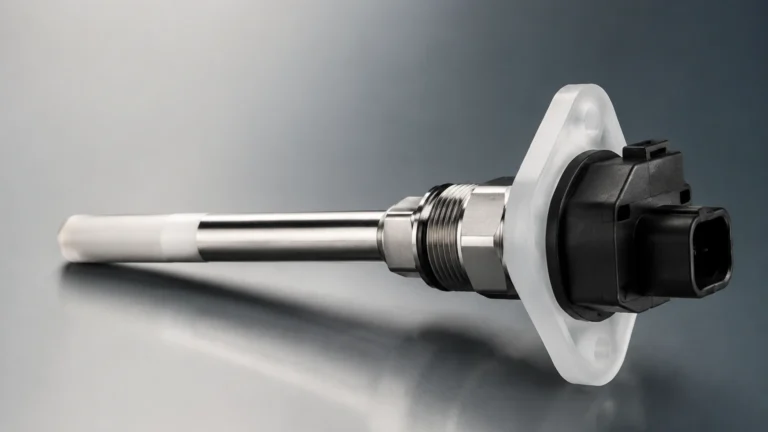
Io Link Temperature Sensor
Io Link Temperature Sensor
In the landscape of modern industrial automation, the transition from traditional analog signaling to digital communication has redefined how process data is collected and utilized. The io link temperature sensor stands at the forefront of this evolution, offering a standardized, point-to-point communication interface (IEC 61131-9) that bridges the gap between field-level sensors and higher-level control systems. Unlike conventional 4-20 mA or 0-10 V transmitters, IO-Link enabled devices provide a wealth of diagnostic data, remote parameterization capabilities, and immunity to electromagnetic interference, making them indispensable in complex process environments.
For engineers and plant managers focused on precision, particularly in applications involving fluid dynamics and storage, understanding the integration of temperature data is critical. Temperature fluctuations directly impact the density and volume of liquids, which in turn affects the accuracy of level measurement instruments such as those found on the Welk Main Page. This article explores the technical principles, selection criteria, and practical implementation of IO-Link temperature technology within industrial frameworks.
Measurement Principles and Digital Conversion
To appreciate the value of an io link temperature sensor, one must first understand the underlying sensing technologies and how IO-Link transforms their output. Most industrial temperature sensors rely on one of two physical principles: Resistance Temperature Detectors (RTDs) or Thermocouples.
Resistance Temperature Detectors (RTDs)
RTDs, most commonly Pt100 or Pt1000 sensors, operate on the principle that the electrical resistance of a metal (platinum) increases predictably as temperature rises. In a standard setup, this resistance is measured and converted into an analog signal. However, in an IO-Link configuration, the analog-to-digital (A/D) conversion occurs directly within the sensor head. This localized conversion eliminates the risk of signal degradation caused by long cable runs or environmental noise.
Thermocouples
Thermocouples utilize the Seebeck effect, where two dissimilar metals joined at one end produce a voltage proportional to the temperature difference between the junction and the reference point. While thermocouples are preferred for extremely high-temperature ranges, they are susceptible to electrical interference. An io link temperature sensor utilizing a thermocouple compensates for this by digitizing the millivolt signal immediately, ensuring that the data transmitted to the IO-Link Master is robust and accurate.
The IO-Link Communication Layer
Once the physical temperature is converted into a digital value, the IO-Link protocol packages this information along with "cyclical" and "acyclical" data.
- Cyclic Data: The actual process value (temperature) sent to the PLC at high speeds.
- Acyclic Data: Device parameters, serial numbers, and diagnostic information (e.g., internal device temperature, operating hours, or wire-breakage alerts).
The Role of Temperature in Level Measurement Accuracy
In the context of industrial instrumentation, temperature is rarely a standalone variable. For a manufacturer like Welk, which specializes in radar level meters and ultrasonic sensors, temperature data is a vital compensation factor. The accuracy of many level measurement technologies is intrinsically linked to the thermal state of the medium or the environment.
Ultrasonic Level Sensors
Ultrasonic sensors measure the time it takes for a sound wave to travel to the liquid surface and back. However, the speed of sound in air changes by approximately 0.17% per degree Celsius. Without precise data from a nearby io link temperature sensor, an ultrasonic system might report a level error of several centimeters during a significant shift in ambient temperature. Integrating IO-Link allows the PLC to receive high-resolution temperature updates and apply real-time compensation algorithms to the level data.
Hydrostatic Level Transmitters
Hydrostatic sensors measure the pressure exerted by a liquid column to determine its height. Because the density of a liquid changes with temperature, a fixed density calculation will lead to inaccuracies if the process fluid heats or cools. By utilizing an io link temperature sensor in tandem with a hydrostatic transmitter, operators can calculate the exact density at any given moment, ensuring the level reading remains precise regardless of thermal expansion.
Technical Evaluation and Selection Criteria
Selecting the correct io link temperature sensor requires a detailed analysis of the process requirements and the physical environment. Engineers should consult the following technical parameters during the specification phase:
1. Measuring Range and Accuracy
Standard industrial IO-Link sensors typically cover a range from -50°C to +150°C for general applications, with specialized probes reaching +250°C or higher. Accuracy is often defined in terms of "Class A" or "Class B" (per IEC 60751). For high-precision chemical processing, a Class A Pt100 sensor with an IO-Link interface is recommended to maintain a tolerance of ±(0.15 + 0.002|t|)°C.
2. Process Connections and Probe Length
The physical integration of the sensor is as important as its electronics. Common connections include G1/2 threads, NPT, or hygienic Tri-Clamp fittings for food and pharmaceutical use. The probe length (immersion depth) must be sufficient to reach the moving part of the process flow to avoid "dead zones" where stagnant liquid might not reflect the true process temperature.
3. Housing and Protection Ratings
In harsh environments, such as water treatment or oil and gas applications, the sensor housing should be constructed from 316L stainless steel. Look for IP67 or IP69K ratings if the sensor will be subjected to high-pressure washdowns or outdoor exposure.
Selection Summary Table
| Feature | Specification | Importance |
| :— | :— | :— |
| Sensing Element | Pt100 / Pt1000 | Determines base accuracy and stability. |
| Interface | IO-Link V1.1 | Ensures compatibility with modern Masters and COM3 speeds. |
| Response Time (t90) | < 2 seconds | Critical for fast-changing thermal processes. |
| Data Storage | Supported | Allows automatic parameter upload upon sensor replacement. |
| Output Options | IO-Link + 4-20mA | Provides redundancy for legacy systems. |
Installation Guidelines and Best Practices
To ensure the longevity and reliability of an io link temperature sensor, specific installation protocols must be followed. Improper placement is the leading cause of measurement drift and premature failure.
Immersion Depth
A general engineering rule is that the sensor probe should be immersed to a depth of at least 10 times its diameter (for liquids) or 15 times its diameter (for gases). This prevents "stem conduction," where the temperature of the ambient air outside the tank or pipe travels down the sensor body and skews the internal reading.
Wiring and Connectivity
One of the primary benefits of IO-Link is the use of standard, unshielded 3-wire M12 cables. While traditional analog sensors require expensive shielded cables to prevent noise, the digital nature of IO-Link allows for cost-effective wiring. However, the cable length between the sensor and the IO-Link Master must not exceed 20 meters. If longer distances are required, a fieldbus-linked Master should be placed closer to the process.
Parameterization and IODD Files
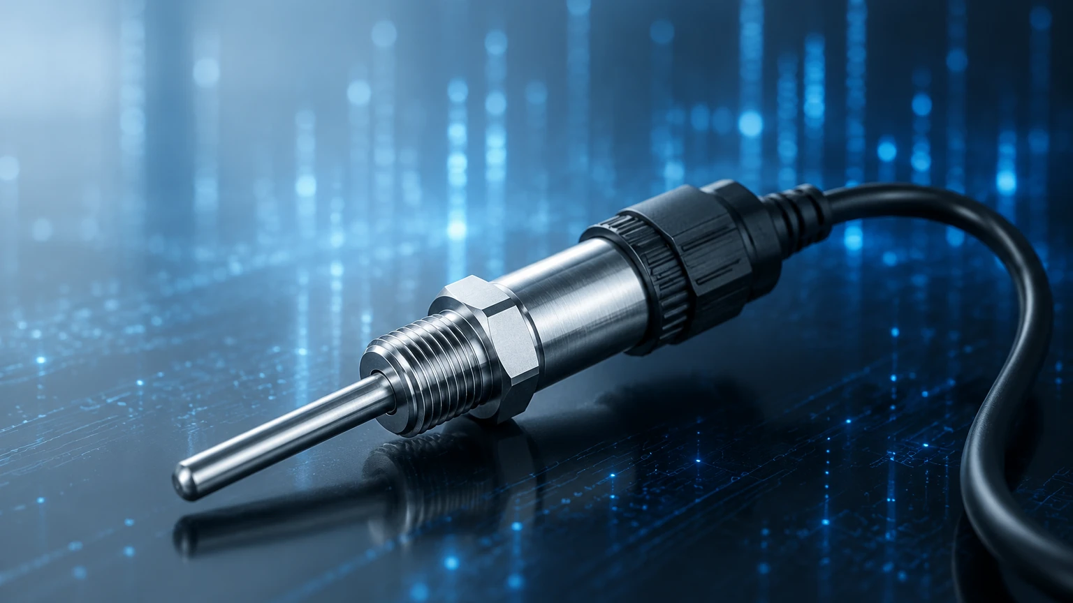
Every io link temperature sensor comes with an IODD (IO Device Description) file. This file contains all the information about the device's identity, parameters, and data structure. Before commissioning, the IODD must be uploaded to the IO-Link Master's configuration tool. This allows the engineer to set alarm thresholds, units (°C/°F/K), and digital filters without needing to access the physical sensor.
Limitations and Operational Challenges
While the io link temperature sensor offers significant advantages, it is not a universal solution for every scenario. Engineering teams must be aware of the following limitations:
1. Distance Constraints: As mentioned, the 20-meter limit between the device and the master can be a hurdle in large-scale facilities. In these cases, distributed IO-Link Master blocks with Ethernet/IP or PROFINET backbones are necessary.
2. Bandwidth: While IO-Link is perfect for temperature, pressure, and level data, it does not have the bandwidth for high-speed vibration analysis or complex imaging data.
3. Initial Complexity: For facilities used to simple "plug-and-play" 4-20mA loops, the initial setup of IODD files and PLC integration requires a higher level of software competency.
Frequently Asked Questions (FAQ)
Q: Can I use an IO-Link temperature sensor in a hazardous area?
A: Yes, there are intrinsically safe (IS) IO-Link sensors available, though they require a compatible IS IO-Link Master or an isolated barrier. Always check the ATEX or IECEx ratings of the specific model.
Q: What happens if the IO-Link communication fails?
A: Most sensors can be configured to provide a "fallback" behavior. Many models offer a secondary analog output (4-20mA) or a switching output that can trigger a safety shutdown if the digital link is lost.
Q: Is it possible to replace a sensor without re-programming the PLC?
A: Yes. If the IO-Link Master supports "Data Storage" (standard in V1.1), it will automatically push the previous sensor's parameters (such as alarm setpoints and offsets) to the new sensor as soon as it is plugged in.
Q: How does this technology improve maintenance cycles?
A: IO-Link sensors provide internal diagnostics. Instead of scheduled manual calibrations, the sensor can report its own health status, allowing for "predictive maintenance"—replacing the sensor only when its internal diagnostics indicate a potential for drift or failure.
Conclusion
The integration of an io link temperature sensor into industrial processes represents a significant step toward data-driven manufacturing. By providing precise, noise-immune digital data, these sensors not only improve the accuracy of individual temperature readings but also enhance the performance of related systems, such as the level measurement solutions provided by Welk.
Whether you are managing a water treatment facility or a chemical processing plant, the ability to remotely configure sensors and access real-time diagnostics reduces downtime and operational costs. For those looking to optimize their measurement infrastructure, reviewing the diverse range of compatible instruments on the Welk Main Page is an excellent starting point for building a more resilient and intelligent process control system.