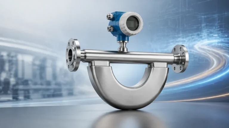
Heat Flow Meter
Heat Flow Meter
In industrial process engineering and thermal management, the ability to quantify energy transfer is as critical as monitoring fluid levels or pressure. A heat flow meter (HFM) is a specialized instrument designed to measure the rate of heat energy transfer through a material or across a surface. Unlike a thermometer, which only measures the thermal state (temperature), a heat flow meter measures the movement of thermal energy, typically expressed in Watts per square meter (W/m²) or BTU per hour per square foot (BTU/h·ft²).
For engineers managing complex systems in water treatment, chemical processing, and oil and gas, understanding heat flow is essential for optimizing insulation, ensuring reactor safety, and improving energy efficiency. This guide explores the principles, applications, and selection criteria for heat flow meters in industrial environments.
Measurement Principles of Heat Flow
To effectively utilize a heat flow meter, one must first understand the physics of thermal transfer. Heat naturally moves from a region of higher temperature to a region of lower temperature through three primary mechanisms: conduction, convection, and radiation. Industrial heat flow meters primarily focus on conductive heat flux.
Fourier’s Law of Heat Conduction
The operation of most heat flow meters is governed by Fourier’s Law, which states that the heat transfer rate through a material is proportional to the negative gradient in the temperature and the area through which the heat flows. Mathematically, it is expressed as:
q = -k · ∇T
Where:
* q is the heat flux (W/m²).
* k is the thermal conductivity of the material (W/m·K).
* ∇T is the temperature gradient.
The Thermopile Sensor
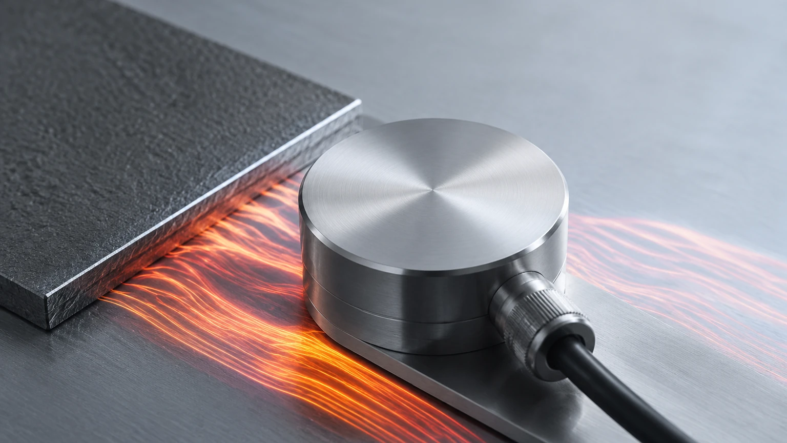
Most commercial heat flow meters employ a thermopile sensor. A thermopile consists of multiple thermocouples connected in series. These thermocouples are embedded within a material of known thermal resistance. As heat passes through the sensor, a small temperature difference is created across the sensor’s thickness. This temperature difference generates a proportional voltage (the Seebeck effect). Because the series connection amplifies the signal, the meter can detect even minute fluctuations in heat transfer.
Industrial Applications and Integration
Heat flow meters are rarely used in isolation; they are typically part of a broader instrumentation strategy that includes level measurement and flow control. For instance, when monitoring a heated storage tank, an engineer might use a Main Page to track volume while simultaneously using heat flow sensors to monitor the efficiency of the tank's steam tracing or insulation jacket.
1. Insulation Performance Testing
In the oil and gas industry, maintaining specific temperatures in pipelines is vital to prevent the formation of hydrates or paraffin waxes. Heat flow meters are used to perform in-situ testing of insulation. By measuring the heat flux escaping through the pipe wall, maintenance teams can identify areas where insulation has degraded or become saturated with moisture before a failure occurs.
2. Chemical Reactor Monitoring
Exothermic and endothermic reactions in chemical processing require precise thermal management. Heat flow meters attached to reactor walls provide real-time data on the heat generated or absorbed by the process. This data is critical for preventing thermal runaway and ensuring product consistency.
3. Building Envelope and HVAC Efficiency
In industrial automation and facility management, HFMs are used to evaluate the R-value (thermal resistance) of building materials. This helps in auditing the energy efficiency of large-scale warehouses and cold storage facilities, where even minor thermal leaks result in significant operational costs.
Technical Selection Criteria
Choosing the right heat flow meter requires an analysis of the environment and the specific thermal dynamics of the application. The following table summarizes key evaluation factors for industrial heat flow sensors.
| Feature | Specification/Consideration | Impact on Measurement |
| :— | :— | :— |
| Temperature Range | -200°C to +1000°C (-328°F to 1832°F) | Determines suitability for cryogenic or furnace applications. |
| Sensitivity | μV/(W/m²) | Higher sensitivity is required for low-flux environments like building insulation. |
| Response Time | Seconds to Minutes | Critical for monitoring transient thermal processes in chemical reactors. |
| Sensor Thickness | 0.1 mm to 5.0 mm | Thinner sensors minimize the "loading effect" (interference with natural heat flow). |
| Environmental Rating | IP67/IP68 or ATEX/IECEx | Necessary for outdoor use or hazardous zones in oil and gas. |
Installation Considerations and Best Practices
The accuracy of a heat flow meter is highly dependent on how it is installed. Improper mounting can introduce thermal contact resistance, leading to significant measurement errors.
Surface Preparation
The surface where the sensor is mounted must be clean and flat. Any air gaps between the sensor and the surface act as powerful insulators, which will cause the meter to under-read the actual heat flux. For industrial pipes and tanks, removing rust, scale, or loose paint is a mandatory first step.
Thermal Interface Materials (TIM)
To eliminate air gaps, engineers should use thermal grease or conductive pads. These materials fill microscopic voids and ensure a continuous thermal path from the measured surface into the sensor. In high-temperature applications, specialized ceramic-based thermal pastes are required.
Avoiding the Loading Effect
When a sensor is placed on a surface, it adds a layer of thermal resistance. If the sensor is too thick or has a much lower thermal conductivity than the surface it is measuring, it will deflect the heat flow, leading to an inaccurate reading. This is known as the "loading effect." In B2B industrial settings, choosing a sensor with a thermal conductivity that closely matches the substrate is preferred.
Wiring and Signal Protection
Because thermopile sensors generate very low millivolt signals, they are susceptible to electromagnetic interference (EMI). Shielded cabling should be used, and the signal wires should be kept away from high-voltage power lines for pumps or agitators. Integration with a high-resolution data logger or a PLC (Programmable Logic Controller) is necessary to convert the raw voltage into a meaningful heat flux value.
Limitations of Heat Flow Measurement
While heat flow meters are powerful tools, they have specific limitations that engineers must account for in their designs:
1. Steady State vs. Transient Flow: Most standard HFMs are calibrated for steady-state conditions. In environments where temperatures fluctuate rapidly, the thermal mass of the sensor itself can cause a lag in data reporting.
2. Point Measurement: An HFM measures heat flux at a specific point. In large industrial systems, such as a 50,000-gallon chemical tank, multiple sensors are often required to gain a representative average of the total heat loss.
3. Radiation Interference: If a sensor is exposed to direct sunlight or high-intensity infrared sources (like a furnace door), the radiant heat can skew the conductive heat flux reading. Reflective shields or coatings may be necessary to isolate the conductive component.
Frequently Asked Questions (FAQ)
Q: Can a heat flow meter measure the thermal conductivity of a liquid?
A: Directly, no. HFMs are typically surface-mount or immersion-probe devices designed to measure flux. To determine the thermal conductivity of a liquid, a guarded hot plate or transient hot wire method is usually employed in a laboratory setting.
Q: How often do heat flow sensors need calibration?
A: In stable industrial environments, annual calibration is standard. However, if the sensor is exposed to extreme temperatures or corrosive chemicals, semi-annual verification is recommended to ensure the thermopile has not degraded.
Q: Is there a difference between a heat flux sensor and a heat flow meter?
A: Technically, the "sensor" is the component that generates the signal, while the "meter" is the complete system including the sensor, the transmitter, and the display/output unit. In B2B procurement, the terms are often used interchangeably.
Conclusion
Integrating heat flow measurement into industrial process monitoring allows for a more granular understanding of energy dynamics. Whether it is ensuring the integrity of insulation in a subsea pipeline or optimizing the cooling cycles of a chemical batch reactor, the heat flow meter provides the data necessary for informed decision-making. When paired with reliable level and flow instrumentation, these devices complete the picture of process efficiency and safety.
For engineers seeking to enhance their facility's monitoring capabilities, it is essential to consult with specialists who understand the intersection of thermal dynamics and industrial automation. To explore a comprehensive range of measurement solutions, including radar and ultrasonic systems that complement thermal monitoring, Review product options and application support to find the right technology for your specific operational requirements.