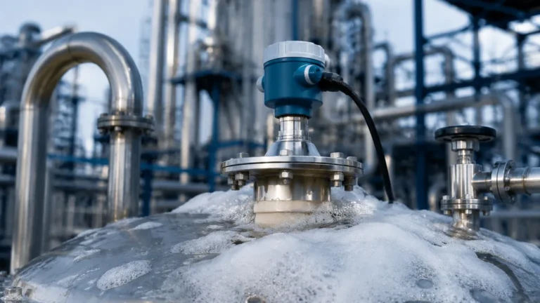
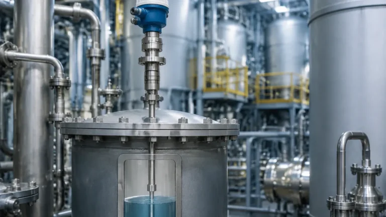
Vega Guided Wave Radar Level Transmitter
Engineering Guide to Vega Guided Wave Radar Level Transmitters
In the field of industrial process automation, precise level measurement is critical for safety, efficiency, and inventory management. Among the various technologies available, the vega guided wave radar level transmitter has established itself as a reliable solution for challenging environments. Utilizing Time Domain Reflectometry (TDR), these instruments provide high-accuracy data even in conditions where traditional non-contact methods might struggle. This guide explores the measurement principles, selection criteria, and installation requirements for guided wave radar (GWR) technology, serving as a technical reference for engineers and procurement specialists.
Understanding the Principle of Guided Wave Radar
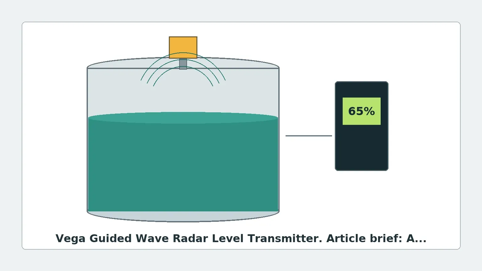
Guided Wave Radar is a contact-based measurement technology. Unlike open-air Radar Level Meters that broadcast electromagnetic waves through space, a GWR transmitter directs high-frequency microwave pulses along a physical waveguide—typically a metal rod, cable, or coaxial tube.
The TDR Measurement Process
1. Pulse Emission: The sensor electronics generate low-energy microwave pulses that travel down the probe at the speed of light.
2. Reflection: When the pulse encounters a change in the dielectric constant ($ε_r$)—specifically the interface between the air/gas phase and the process medium—a portion of the energy is reflected back toward the transmitter.
3. Time-of-Flight Calculation: The transmitter measures the time interval between pulse emission and the reception of the reflected signal. Since the speed of light is constant, the distance to the product surface is calculated using the formula: *Distance = (Speed of Light × Time Delay) / 2*.
4. Level Conversion: By knowing the total tank height (the reference point), the transmitter subtracts the measured distance from the vessel height to determine the actual level.
Because the signal is concentrated along the probe, GWR is significantly less affected by vapor, dust, foam, or turbulent surfaces compared to non-contact radar. It is particularly effective for media with low dielectric constants or in narrow tanks with internal obstructions.
Technical Features of Vega Guided Wave Radar Series
The Vega guided wave radar level transmitter, specifically the VEGAFLEX series, is designed to handle a broad spectrum of liquid and bulk solid applications. These units are characterized by their modularity and ability to withstand extreme process conditions.
Key Performance Specifications
* Measuring Range: Up to 60 meters (75 meters for specific cable versions).
* Process Temperature: Ranges from -196°C to +450°C (-320°F to +842°F).
* Process Pressure: Vacuum up to 400 bar (40 MPa / 5800 psi).
* Accuracy: Typically within ±2 mm, regardless of media density or temperature fluctuations.
Selection Criteria: Choosing the Right Probe
The performance of a GWR transmitter depends heavily on the probe geometry. Selecting the incorrect probe type can lead to signal loss or measurement instability.
Comparison of Probe Types
| Probe Type | Best For | Advantages | Limitations |
| :— | :— | :— | :— |
| Single Rod | Liquids with high dielectric constants, viscous media. | Easy to clean, resistant to buildup. | Sensitive to nearby metal tank walls and nozzles. |
| Cable (Wire) | Tall silos, large tanks, bulk solids. | Flexible installation, long measuring ranges (up to 60m+). | Requires a weight to stay vertical; susceptible to high pull-down forces in solids. |
| Coaxial | Low dielectric liquids ($ε_r$ < 1.6), bypass pipes, turbulent surfaces. | Signal is fully contained; unaffected by tank internals or nozzles. | Not suitable for viscous liquids or media that crystallize/clog. |
| Double Rod | Long-range liquid measurement where coaxial is too heavy. | Better signal-to-noise than single rod. | Susceptible to bridging between rods by solids or debris. |
Dielectric Constant ($ε_r$) Considerations
The dielectric constant of the medium is the most critical factor in GWR selection. Water has a high $ε_r$ (~80), providing a very strong reflection. Hydrocarbons, oils, and liquified gases have low $ε_r$ values (1.4 to 2.5), resulting in weaker reflections. For extremely low dielectric media, a coaxial probe or a "Low Dielectric" software setting is required to ensure the transmitter can track the surface reliably.
Installation Guidelines and Constraints
To ensure the vega guided wave radar level transmitter operates at peak performance, engineers must adhere to specific installation geometry and clearances.
1. Nozzle Dimensions
The nozzle diameter and height significantly impact the initial signal pulse. For rod and cable probes, the nozzle height should be kept as short as possible. If the nozzle is narrow and tall, it may create a "ringing" effect that masks the signal in the upper part of the tank (the Upper Dead Zone). Coaxial probes are immune to nozzle interference.
2. Clearance from Tank Walls and Internals
* Wall Distance: For single rod or cable probes, a minimum distance of 300 mm (12 inches) from the tank wall is recommended to prevent false reflections.
* Internal Obstructions: Probes should be installed away from agitators, heating coils, and ladders. If the probe touches a metal object, it will create a false level signal.
* Inflow: Never install the probe directly in the path of the filling stream. This causes physical wear on the probe and introduces significant signal noise.
3. The Dead Zone (Blocking Distance)
Every GWR sensor has an upper and lower dead zone.
* Upper Dead Zone: The area near the process connection where the signal cannot be accurately measured due to the transition from the transmitter electronics to the probe.
* Lower Dead Zone: The area at the very tip of the probe where the signal reflection becomes non-linear.
Typically, these zones range from 50 mm to 250 mm depending on the probe type and the dielectric of the medium. Engineers must ensure the maximum and minimum process levels fall within the "measurable" range of the probe.
Application Risks and Limitations
While highly versatile, guided wave radar is not a universal solution. Certain conditions can compromise measurement accuracy:
* Media Buildup and Coating: While GWR is better at handling coating than many technologies, excessive buildup of conductive or moist material on the probe can cause signal attenuation or "ghost" levels. In such cases, a single-rod probe is preferred over a coaxial or double-rod design.
* Interface Measurement: GWR is excellent for measuring the interface between two liquids (e.g., oil over water). However, the upper liquid must have a lower dielectric constant than the lower liquid, and the upper layer must be thick enough (typically >100 mm) for the sensor to distinguish the two reflections.
* High Pull-down Forces: In bulk solids applications (sand, grain, cement), the downward force on a cable probe during discharge can be several tons. The tank roof must be reinforced to handle these tensile loads, and the probe must be securely anchored or allowed to swing freely if necessary.
Maintenance and Troubleshooting
One of the primary benefits of the vega guided wave radar level transmitter is its low maintenance requirement. Since there are no moving parts, mechanical wear is non-existent. However, periodic checks are recommended:
1. Signal Strength Monitoring: Modern transmitters provide a signal-to-noise ratio. A declining ratio over time usually indicates probe coating or corrosion.
2. Echo Curve Analysis: Using software like PACTware or the manufacturer's proprietary interface, technicians can view the "Echo Curve." This visual representation of the reflections allows for the masking of false echoes caused by internal tank structures.
3. Probe Inspection: In corrosive environments, the probe should be inspected for pitting or degradation. For PTFE-coated probes, ensure the insulation remains intact to prevent short-circuiting against the medium.
Frequently Asked Questions (FAQ)
Q: Can GWR measure level in a vacuum?
A: Yes. Since electromagnetic waves do not require a medium for travel, GWR is highly effective in vacuum distillation columns and similar vessels. Unlike ultrasonic sensors, it is unaffected by the lack of air.
Q: How does foam affect the measurement?
A: GWR is generally superior to non-contact radar in foamy applications. Depending on the foam density and moisture content, the signal will either pass through the foam to the liquid surface or reflect off the top of the foam. For thick, heavy foam, specialized signal processing is often employed.
Q: Can I cut the probe to length in the field?
A: Many rod and cable versions of the vega guided wave radar level transmitter are field-shortenable. After cutting, the new length must be entered into the sensor configuration to maintain accuracy. Coaxial probes are more difficult to modify in the field and should be ordered to the exact length required.
Q: Is GWR suitable for high-pressure steam?
A: Yes, but with a caveat. High-pressure steam can change the propagation speed of the microwave pulse, leading to measurement errors. For these applications, a transmitter with "Steam Compensation" (using a reference reflection) is required to maintain accuracy.
Conclusion
The vega guided wave radar level transmitter represents a robust choice for industrial level measurement, offering high precision in the face of turbulence, vapors, and varying pressures. By understanding the dielectric properties of the media and adhering to strict installation clearances, engineers can ensure long-term, maintenance-free operation. For applications where contact is not permissible, or for broader comparisons of microwave-based sensing, exploring a wider range of Radar Level Meters can help identify the optimal balance between cost and performance for specific process needs.