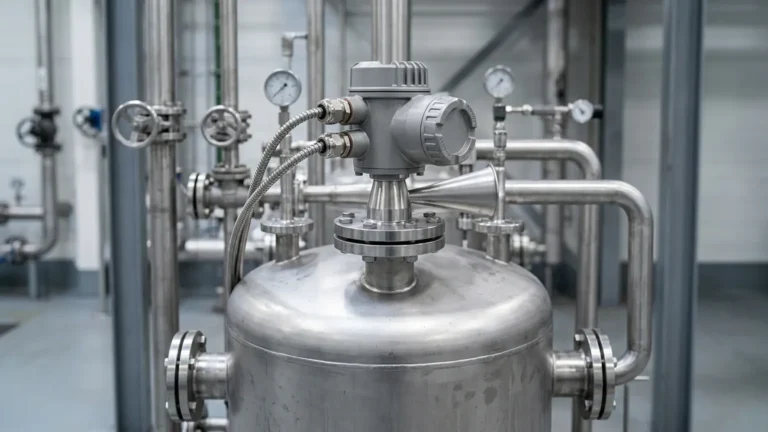
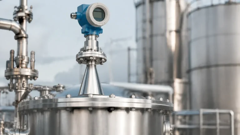
What Is Guided Wave Radar Level Transmitter
What Is Guided Wave Radar Level Transmitter: A Technical Engineering Guide
In the field of industrial process automation, achieving precise and repeatable level measurement is critical for safety, inventory management, and process efficiency. Among the various technologies available, the guided wave radar (GWR) transmitter has emerged as a robust solution for challenging environments. This guide explores the fundamental question—what is guided wave radar level transmitter—while detailing its principles, advantages, and practical application in modern industry.
Guided wave radar is a contact-based level measurement technology that utilizes electromagnetic pulses directed along a physical waveguide (a probe). Unlike non-contact Radar Level Meters that broadcast signals through the air, GWR keeps the energy concentrated around the probe, making it exceptionally reliable in conditions involving turbulence, foam, or narrow tank geometries.
The Core Measurement Principle: Time Domain Reflectometry (TDR)
To understand what is guided wave radar level transmitter technology, one must first understand Time Domain Reflectometry (TDR). This principle is similar to that used in cable testing to locate breaks in underground wires.
1. Pulse Emission: The transmitter electronics generate low-energy, high-frequency electromagnetic pulses (typically in the gigahertz range).
2. Guided Propagation: These pulses are coupled onto a probe (the waveguide) and travel downward at the speed of light.
3. Reflection (The Echo): When the pulse reaches the surface of the medium being measured, a portion of the pulse energy is reflected back toward the transmitter. This reflection occurs because of a change in the dielectric constant ($ε_r$) between the upper medium (usually air or gas) and the process medium (liquid or solid).
4. Time-of-Flight Calculation: The transmitter measures the time interval between the pulse emission and the receipt of the reflected echo. Since the speed of light is constant, the distance to the product surface is calculated using the formula:
*Distance = (Speed of Light × Time-of-Flight) / 2.*
The level of the material is then determined by subtracting the measured distance from the total tank height (the zero point calibration).
Guided Wave Radar vs. Non-Contact Radar Level Meters
While both technologies fall under the category of radar level measurement, GWR offers distinct mechanical and physical advantages in specific scenarios. Non-contact radar emits a conical beam that can be obstructed by internal tank structures like ladders, agitators, or heating coils. In contrast, GWR focuses the signal along the probe, significantly reducing the "keep-out" zone required for accurate measurement.
| Feature | Guided Wave Radar (GWR) | Non-Contact Radar |
| :— | :— | :— |
| Measurement Type | Contact | Non-contact |
| Signal Path | Concentrated along a probe | Conical beam spread |
| Foam Resistance | Excellent (penetrates most foam) | Variable (foam can absorb signals) |
| Turbulence | Highly stable | May require signal filtering |
| Internal Obstructions | Ignores most objects >300 mm from probe | Requires clear line-of-sight |
| Minimum Dielectric | Can measure down to ε_r 1.4 | Generally requires ε_r > 1.9 |
Probe Selection and Configuration
The performance of a GWR transmitter is heavily dependent on the type of probe selected. Welk provides several configurations to suit different media and vessel types.
1. Single Rod or Cable Probes
These are the most common and cost-effective. They are easy to clean and suitable for liquids with higher dielectric constants or for solids (using a cable). However, they are more sensitive to electromagnetic interference from tank walls or internal structures. A minimum clearance of 300 mm (12 inches) from the tank wall is typically recommended.
2. Twin Rod or Twin Cable Probes
By using two parallel conductors, the electromagnetic field is more tightly contained between the rods. This makes them suitable for measuring liquids with lower dielectric constants and reduces the influence of the tank wall. They are, however, prone to bridging if the medium is viscous or contains solids.
3. Coaxial Probes
The coaxial probe consists of a central rod inside an outer perforated tube. This provides the highest signal-to-noise ratio and is completely unaffected by tank internals or nozzles. It is the ideal choice for low-dielectric fluids (like liquefied gases) and highly turbulent surfaces. The primary limitation is that it should only be used with clean, low-viscosity liquids to prevent clogging of the outer tube.
Interface Level Measurement Capabilities
One of the unique answers to "what is guided wave radar level transmitter used for" is interface measurement. GWR is one of the few technologies capable of measuring both the total level and the interface level between two immiscible liquids (e.g., oil and water) simultaneously.
When the radar pulse hits the upper liquid layer (low dielectric, like oil), a portion of the signal reflects. The remaining energy continues through the oil and reflects off the lower liquid layer (high dielectric, like water). This allows the transmitter to output two distinct signals, providing critical data for separation tanks and decanters.
Engineering Selection Criteria
When specifying a GWR transmitter for an industrial project, engineers must evaluate several technical boundaries:
* Dielectric Constant (ε_r): This is the most critical factor. Water has a high ε_r (~80), providing a strong reflection. Hydrocarbons have low ε_r (1.7 to 2.5), requiring more sensitive electronics or coaxial probes.
* Process Temperature and Pressure: Standard GWR units handle up to 200°C (392°F), but high-temperature versions with ceramic seals can withstand up to 450°C (842°F) and pressures exceeding 400 bar (5800 psi).
* Vessel Height: Cable probes can extend up to 60 meters (approx. 196 feet) for tall silos, while rigid rods are typically limited to 6 meters (approx. 20 feet) due to shipping and installation constraints.
* Chemical Compatibility: Probes are commonly manufactured from 316L stainless steel, but corrosive applications may require Hastelloy, Monel, or PTFE coating.

Installation Best Practices and Geometric Constraints
To ensure the longevity and accuracy of the instrument, follow these engineering guidelines during installation:
1. Nozzle Dimensions: The height and diameter of the mounting nozzle can affect the signal near the top of the tank. Ensure the nozzle diameter is large enough to prevent "ringing" or false echoes at the launch point.
2. The Upper Dead Zone (Blocking Distance): There is a region at the very top of the probe (typically 50 mm to 200 mm) where measurement is not possible or accurate. The process should be designed so the maximum liquid level does not enter this zone.
3. The Lower Dead Zone: At the very tip of the probe, the signal can be distorted by reflections from the probe end. A transition zone of approximately 50 mm to 100 mm should be accounted for at the bottom of the tank.
4. Probe Anchoring: In tanks with high agitation or flow, cable probes must be weighted or anchored to the bottom to prevent mechanical fatigue or contact with the tank wall. If anchored, an insulated tensioning weight is often used to maintain signal integrity.
Limitations and Maintenance Considerations
While highly versatile, GWR is not a "one-size-fits-all" solution. Engineers should be aware of the following limitations:
* Material Build-up: While GWR can handle some coating, significant build-up of conductive material between a twin-rod or inside a coaxial probe will cause measurement errors. Single rod probes are more resistant to this.
* Mechanical Stress: In heavy solids applications (like grain or coal), the downward pull (tensile load) on a cable probe can be several tons. The tank roof and the transmitter mounting must be engineered to support these loads.
* Vapor Space Composition: Extremely high-pressure steam can change the propagation speed of the radar pulse, requiring a "gas phase compensation" reference to maintain accuracy.
Frequently Asked Questions (FAQ)
Q: Can guided wave radar measure dry powders?
A: Yes. GWR is excellent for powders and granules. A cable probe is typically used to withstand the pull-down forces of the material. The dielectric constant of the powder must be at least 1.4.
Q: Does the tank material matter?
A: For single rod probes, a metallic tank provides a better reference. In plastic or fiberglass tanks, a coaxial probe or a dual-rod probe is recommended, or a large metal flange/mounting plate must be used to provide a proper launch ground.
Q: How does foam affect the measurement?
A: In most cases, the radar pulse passes through the foam and reflects off the liquid surface. However, very dense, metallic, or wet foam may produce a signal reflection of its own. GWR is generally much more effective in foamy applications than ultrasonic or non-contact radar.
Q: Is calibration required on-site?
A: Most modern GWR transmitters are pre-calibrated from the factory based on the ordered probe length. On-site configuration usually only involves setting the 4-20mA scaling and defining the tank zero point.
Conclusion
Guided wave radar represents a pinnacle of reliability for contact level sensing. By understanding what is guided wave radar level transmitter technology and its reliance on TDR, engineers can solve complex level challenges in chemical processing, water treatment, and oil and gas production. When selected and installed correctly, these instruments provide maintenance-free operation and high-precision data even in the most demanding process conditions. For more information on selecting the right configuration for your facility, explore our comprehensive range of Radar Level Meters and technical resources.
Download What Is Guided Wave Radar Level Transmitter as a PDF