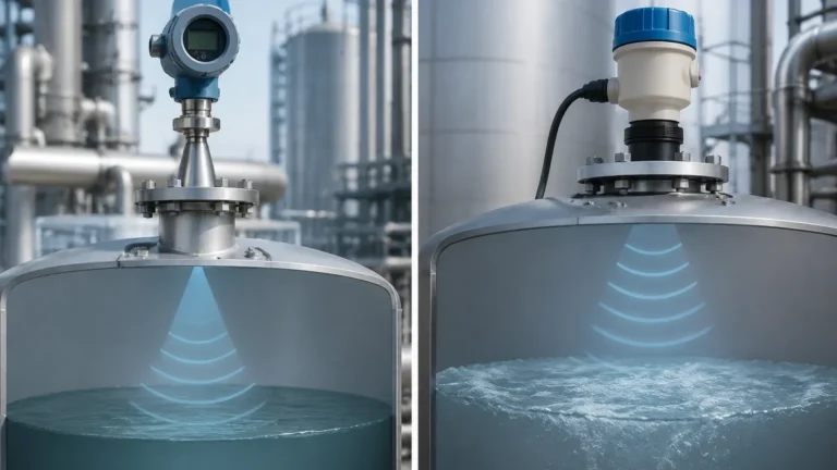
Vega Radar Level Transmitter Calibration
Vega Radar Level Transmitter Calibration: A Professional Engineering Guide
In the realm of industrial process automation, the accuracy of level measurement is critical for operational safety, inventory management, and process efficiency. Among the various technologies available, Radar Level Meters have become the industry standard for non-contact measurement in challenging environments. This guide focuses on the technical nuances of vega radar level transmitter calibration, providing engineers and technicians with a comprehensive framework for commissioning and maintaining these sophisticated instruments.
Understanding the Principles of Radar Level Measurement
Before detailing the calibration process, it is essential to understand the underlying physics. Radar level transmitters typically utilize one of two primary technologies: Pulse Radar or Frequency Modulated Continuous Wave (FMCW).
Pulse Radar vs. FMCW
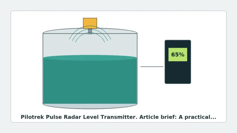
Pulse radar instruments emit short microwave pulses toward the medium. The time elapsed between the emission and the reception of the reflected signal (Time of Flight) is used to calculate the distance. FMCW radar, however, emits a continuous signal with a constantly changing frequency. The difference between the emitted frequency and the received frequency at any given moment is proportional to the distance. Modern high-frequency instruments, particularly those operating at 80 GHz, predominantly use FMCW due to its superior signal resolution and narrower beam angle, which minimizes interference from internal tank structures.
Signal Reflection and Dielectric Constant
The reliability of the measurement depends on the Dielectric Constant (DK) of the medium. Materials with high DK values (e.g., water-based liquids) reflect radar waves strongly, while materials with low DK values (e.g., hydrocarbons or solids like plastic pellets) allow waves to penetrate deeper, resulting in weaker reflections. Calibration must account for these variations to ensure the transmitter correctly identifies the product surface.
Vega Radar Level Transmitter Calibration: Step-by-Step Procedure
Calibration of a Vega radar transmitter—such as the VEGAPULS series—can be performed via the local display and adjustment module (PLICSCOM), a PC with PACTware/DTM software, or wirelessly via Bluetooth using the VEGA Tools app.
1. Initial Setup and Parameterization
The first step in vega radar level transmitter calibration is defining the basic vessel geometry. This is often referred to as "dry calibration" because it can be performed without the medium present.
* Unit Selection: Define the measurement units (e.g., meters, millimeters, or feet).
* Vessel Shape: Select the tank head type (e.g., flat, dished, or conical) to allow the transmitter to calculate volume correctly if required.
* Medium Selection: Categorize the medium as a liquid or a bulk solid. This adjusts the signal processing algorithms for the expected surface behavior.
2. Adjustment (Min/Max Calibration)
Adjustment defines the relationship between the measured distance and the output signal (typically 4-20mA).
* Min. Adjustment (100% Empty): This is the distance from the sensor reference plane (usually the bottom of the flange or thread) to the bottom of the vessel. For example, if a tank is 10 meters (32.8 ft) deep, the Min. Adjustment is set to 10.000 m. At this distance, the transmitter will output 4mA.
* Max. Adjustment (100% Full): This is the distance from the sensor reference plane to the maximum filling level. If the maximum level is 0.5 meters below the sensor, the Max. Adjustment is set to 0.500 m. At this distance, the transmitter will output 20mA.
3. False Signal Suppression (Mapping)
One of the most critical steps in calibrating Radar Level Meters is the creation of a "false signal suppression" map. This process records echoes from fixed internal structures—such as agitators, heating coils, or ladders—and instructs the transmitter to ignore them.
* Procedure: Ideally, mapping should be performed when the vessel is empty or at the lowest possible level. The transmitter scans the entire height of the tank, identifies all stationary reflections, and creates a threshold curve. Any signal below this curve is disregarded, ensuring only the true product surface echo is tracked.
4. Advanced Signal Tuning
For complex applications, engineers may need to adjust the "Echo Tracking" or "Sensitivity" settings. If the medium has a low dielectric constant, increasing the sensitivity can help, though it may also increase noise. Conversely, in turbulent applications, increasing the damping (integration time) can stabilize the output signal.
Selection Criteria for Industrial Radar Level Meters
Choosing the right instrument is as important as the calibration itself. The following table outlines selection criteria based on typical industrial requirements.
| Feature | 26 GHz Radar | 80 GHz Radar | Guided Wave Radar (GWR) |
| :— | :— | :— | :— |
| Beam Angle | Wide (approx. 10° – 20°) | Narrow (approx. 3° – 8°) | N/A (signal follows probe) |
| Accuracy | ±2 mm to ±5 mm | ±1 mm | ±2 mm |
| Max Range | Up to 30 m (98.4 ft) | Up to 120 m (393.7 ft) | Up to 75 m (246 ft) |
| Dust/Vapor Resistance | Moderate | High | Very High |
| Installation | Flexible | Very Flexible (small nozzles) | Restricted (requires probe clearance) |
| Best Use Case | Large storage tanks | Small vessels with internals | Low DK liquids, interface measurement |
Installation Considerations and Constraints
Proper installation is the foundation of successful calibration. Even the most precise vega radar level transmitter calibration cannot compensate for a poorly positioned sensor.
1. Nozzle Design: The nozzle height should be kept to a minimum. If the nozzle is too long or narrow, it can create "ringing" or internal reflections that interfere with the near-range measurement (the blocking distance).
2. Wall Distance: The sensor should not be mounted too close to the vessel wall. As a rule of thumb, maintain a distance of at least 200 mm (7.87 in) or 1/10th of the vessel height from the wall to avoid interference from weld seams or build-up.
3. Obstruction Avoidance: Ensure the radar beam path is clear of inflow streams. If the product falls through the radar beam, it will cause signal erraticism.
4. Antenna Alignment: For bulk solids, an aiming flange (swivel holder) is often necessary to align the antenna perpendicular to the angle of repose of the material, maximizing the reflected signal strength.

Limitations and Application Risks
While radar is highly versatile, certain conditions present risks to measurement accuracy:
* Heavy Foam: Dense, thick foam can absorb radar signals entirely. In such cases, a Guided Wave Radar or a specialized low-frequency pulse radar may be required.
* Extremely Low Dielectric Media: For media with a DK < 1.4 (e.g., liquid nitrogen or certain solvents), the reflection may be too weak for standard non-contact radar. Guided Wave Radar is typically the preferred alternative here.
* Condensation and Build-up: While 80 GHz radars handle condensation better than older models, heavy crystalline build-up on the antenna can still attenuate the signal. Regular inspection or the use of an air purge connection is recommended in these environments.
Frequently Asked Questions (FAQs)
How often should a radar level transmitter be recalibrated?
In stable processes, radar transmitters are virtually maintenance-free. However, for regulated industries (e.g., pharmaceutical or food and beverage), annual calibration verification is standard. Recalibration is also necessary if the vessel's internal geometry changes or if the medium is replaced with one of a significantly different dielectric constant.
Can I calibrate the transmitter while the tank is full?
Yes, but with limitations. You can perform the Min/Max adjustment and basic parameterization. However, you cannot perform a full false signal suppression (mapping) for the area covered by the liquid. The mapping will only be valid for the empty space above the current level.
What is the "Blocking Distance"?
The blocking distance (or dead zone) is the area immediately below the sensor where measurement is not possible. For most Radar Level Meters, this ranges from 0 to 250 mm (0 to 9.8 in). It is vital to ensure the Max. Adjustment (100% full) does not enter this zone.
What software is needed for Vega calibration?
Vega instruments use PACTware as the frame application, which requires the specific Device Type Manager (DTM) for the sensor model. Alternatively, the VEGA Tools app via Bluetooth is increasingly popular for field adjustments due to its intuitive interface.
Conclusion
Successful vega radar level transmitter calibration requires a blend of theoretical knowledge and practical application. By correctly defining vessel parameters, performing accurate Min/Max adjustments, and meticulously mapping out false echoes, engineers can ensure long-term reliability in even the most demanding industrial environments. When selecting equipment, always consider the specific dielectric properties of your medium and the physical constraints of your vessel to choose the most appropriate radar frequency and antenna design.