Ultrasonic Flowmeters
Ultrasonic Flowmeters
Ultrasonic flowmeters have become a cornerstone of modern industrial process control, offering a non-intrusive method for measuring the volumetric flow rate of liquids and gases. Unlike traditional mechanical meters that rely on moving parts—which are prone to wear and pressure drops—ultrasonic technology utilizes acoustic waves to determine velocity. This engineering guide explores the fundamental principles, selection criteria, and installation requirements for ultrasonic flowmeters within industrial environments.
Measurement Principles
Ultrasonic flow measurement is primarily based on two distinct physical phenomena: the Transit-Time difference and the Doppler Effect. Understanding these principles is the first step in selecting the correct instrument for a specific application.
Transit-Time Method
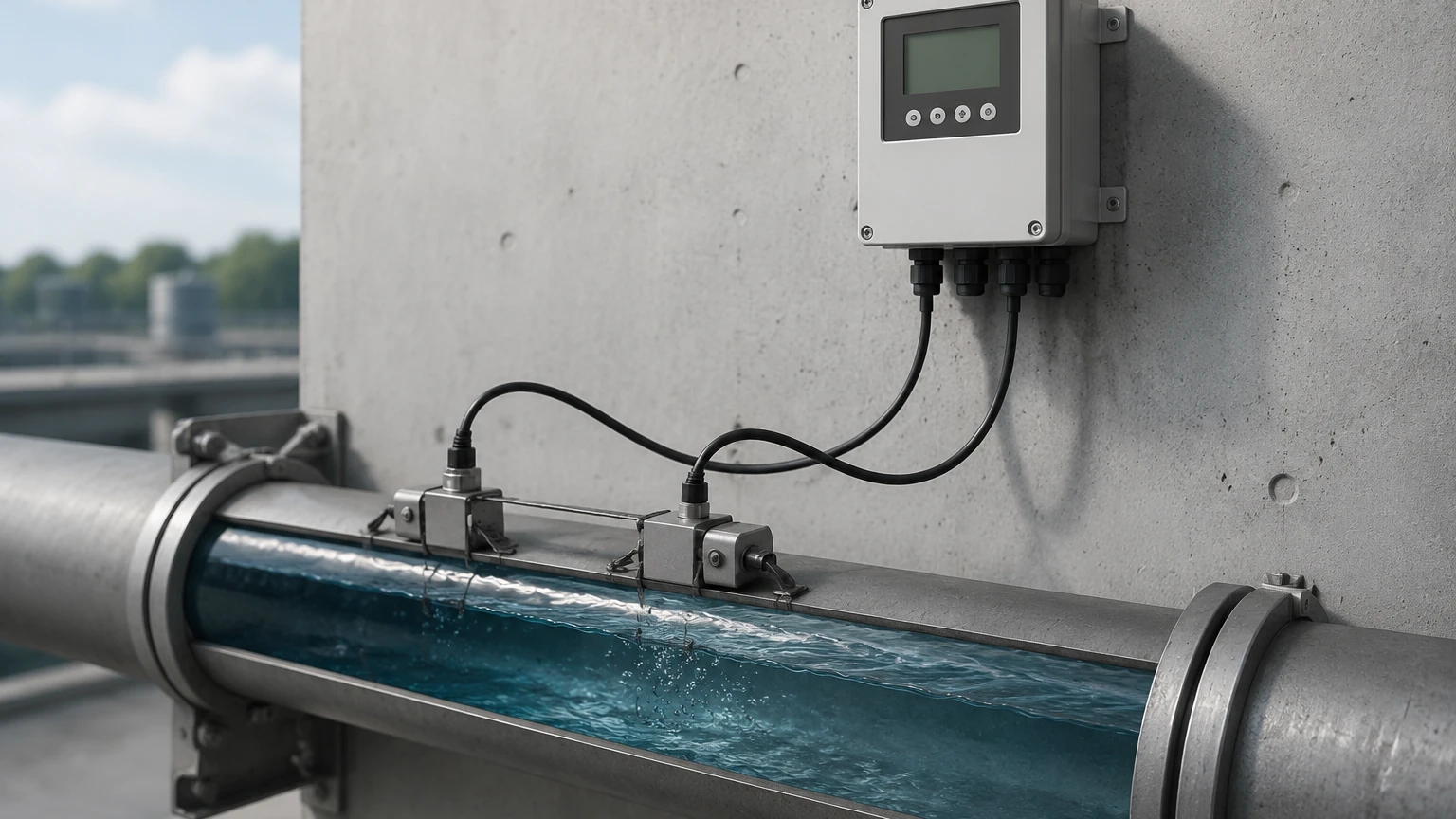
Transit-time ultrasonic flowmeters operate by transmitting and receiving ultrasonic pulses between two transducers. These transducers are typically mounted on the outside of a pipe or integrated into a spool piece. One transducer sends a signal downstream (with the flow), while the other sends a signal upstream (against the flow).
Because the sound waves traveling with the flow move faster than those traveling against it, a time difference ($Δt$) occurs. This time difference is directly proportional to the velocity of the fluid. The internal microprocessor calculates the flow velocity and, by incorporating the pipe’s cross-sectional area, determines the volumetric flow rate. This method is highly accurate for clean liquids where the sound can travel through the medium without significant scattering.
Doppler Effect Method
Doppler flowmeters rely on the reflection of sound waves off moving discontinuities within the fluid, such as suspended solids or entrained air bubbles. The transducer emits an ultrasonic signal of a known frequency. When this signal hits a moving particle, it reflects back to the receiver at a shifted frequency.
This frequency shift (the Doppler shift) is proportional to the velocity of the particles. While the Doppler method is less accurate than the transit-time method for high-precision billing, it is indispensable for "dirty" liquids, slurries, and aerated fluids that would otherwise block a transit-time signal.
Types of Ultrasonic Flowmeters
Industrial applications generally categorize these instruments by their mounting configuration and transducer design.
Clamp-On Flowmeters
Clamp-on models are mounted to the exterior of the pipe. They are favored for retrofit applications because they do not require cutting the pipe or halting the process. These systems are ideal for high-pressure or corrosive environments where wetted parts would be at risk. However, they require precise alignment and the use of acoustic coupling compounds (such as silicone grease or epoxy) to ensure the signal passes through the pipe wall efficiently.
Inline (Wetted) Flowmeters
Inline ultrasonic flowmeters involve transducers that are in direct contact with the fluid or mounted within a factory-calibrated spool piece. These provide the highest accuracy because the path length and geometry are fixed and known. They are commonly used in custody transfer applications and water distribution networks where long-term stability is critical.
Key Evaluation Criteria for Selection
Choosing the right ultrasonic flowmeter requires a detailed analysis of the process conditions. Before proceeding with a procurement, engineers should evaluate the following factors:
1. Fluid Composition: Is the liquid clean or does it contain solids? Transit-time meters require <2% total suspended solids (TSS), whereas Doppler meters require at least 100 ppm of particles larger than 100 microns.
2. Pipe Material and Liner: Ultrasonic signals must pass through the pipe wall. Materials like carbon steel, stainless steel, and PVC are excellent conductors. However, pipes with loose liners (like some teflon-lined pipes) or concrete-lined pipes can create air gaps that attenuate the signal.
3. Flow Profile: Ultrasonic meters are sensitive to turbulence. Ensuring a fully developed flow profile is essential for accuracy.
4. Temperature and Pressure: High temperatures can affect the speed of sound in the fluid and the integrity of the transducer's piezoelectric crystals.
Selection Matrix: Transit-Time vs. Doppler
| Feature | Transit-Time Flowmeters | Doppler Flowmeters |
| :— | :— | :— |
| Fluid Type | Clean liquids, water, oils | Slurries, wastewater, aerated liquids |
| Typical Accuracy | ±0.5% to ±1% of reading | ±2% to ±5% of reading |
| Min. Particle Count | None (prefers clean) | >100 ppm |
| Pipe Size Range | 10 mm to 5000 mm | 25 mm to 5000 mm |
| Installation | Clamp-on or Inline | Usually Clamp-on |
Installation Considerations and Best Practices
Proper installation is the most critical factor in achieving the rated accuracy of an ultrasonic flowmeter. Even the most advanced signal processing cannot compensate for a poorly placed sensor.
Straight Pipe Requirements
To ensure a stable and predictable flow profile, ultrasonic flowmeters require a specific length of straight pipe before and after the sensor. The standard recommendation is at least 10 diameters (10D) of straight pipe upstream and 5 diameters (5D) downstream from any elbows, valves, or pumps. If the upstream disturbance is a pump or a partially open valve, the requirement may increase to 20D or 30D.
Mounting Orientations
For horizontal pipes, transducers should be mounted at the 3 o'clock and 9 o'clock positions (the "sides" of the pipe). Mounting at the top (12 o'clock) risks signal loss due to air pockets, while mounting at the bottom (6 o'clock) risks signal interference from sediment buildup.
Acoustic Coupling
For clamp-on installations, the interface between the transducer and the pipe must be free of air. Surface preparation involves removing rust, scale, or thick paint. A coupling gel is applied to fill microscopic voids. In permanent installations, solid coupling pads or specialized clamps are used to maintain pressure over time.
Limitations and Common Risks
While highly versatile, ultrasonic flowmeters are not universal solutions. Engineers must be aware of the following limitations:
* Signal Attenuation: Highly viscous liquids or fluids with high concentrations of entrained gases can absorb the ultrasonic signal, leading to a "signal lost" error.
* Reynolds Number Sensitivity: The flow profile changes as the fluid moves from laminar to turbulent flow. Most modern meters include compensation algorithms for the Reynolds number, but accuracy may dip in the transition zone.
* Pipe Wall Condition: Internal scaling or heavy corrosion can scatter the signal. In older piping systems, a thickness gauge should be used to verify the actual wall thickness before programming the flowmeter.
Industrial Applications
Ultrasonic flowmeters are utilized across various sectors due to their reliability and low maintenance requirements:
* Water and Wastewater: Monitoring influent and effluent flows, leak detection in large diameter mains, and chemical dosing.
* Chemical Processing: Measuring corrosive or hazardous liquids where non-contact measurement prevents sensor degradation.
* Oil and Gas: Used for produced water measurement and, in high-end multi-path configurations, for custody transfer of natural gas and crude oil.
* HVAC and Energy Management: Measuring chilled water flow and heat transfer in district cooling systems.
As industrial automation evolves, the integration of these meters into digital ecosystems via Modbus, HART, or Profibus allows for real-time monitoring and predictive maintenance. For professionals looking to integrate these technologies into their facilities, reviewing specialized product options and application support on the Main Page is a recommended next step to ensure the hardware matches the specific environmental demands.
Frequently Asked Questions (FAQ)
Q: Can ultrasonic flowmeters measure gas flow?
A: Yes, but gas measurement requires specialized high-frequency transducers and often higher power signals because gas is much less dense than liquid, making it a poor conductor of sound.
Q: Do I need to recalibrate the meter if I move it to a different pipe?
A: If it is a clamp-on meter, you must re-enter the new pipe's parameters (diameter, wall thickness, material). While the factory calibration of the electronics remains valid, the system's accuracy depends on the accuracy of the physical data you provide.
Q: How does viscosity affect measurement?
A: Extremely high viscosity can dampen the ultrasonic signal and alter the flow profile. Most transit-time meters can handle moderate viscosities, but they require a Reynolds number correction factor, which is usually handled by the meter's software.
Q: What is the lifespan of an ultrasonic flowmeter?
A: Since there are no moving parts to wear out, the electronics and transducers can last 10 to 15 years or more. The primary maintenance for clamp-on models is periodically checking the coupling gel to ensure it hasn't dried out.
Conclusion
Ultrasonic flowmeters represent a sophisticated yet practical solution for modern fluid dynamics challenges. By leveraging acoustic principles, they provide a maintenance-free, highly accurate measurement path that respects the integrity of the piping system. When selected based on fluid characteristics and installed with strict adherence to straight-run requirements, they offer one of the highest returns on investment in the field of industrial instrumentation.