Heater Thermometer
Heater Thermometer
In industrial process heating, the ability to monitor thermal energy accurately is critical for both operational efficiency and equipment longevity. A heater thermometer serves as the primary interface between the internal thermal state of a system and the control infrastructure. Whether used in boiler feed systems, heat exchangers, or large-scale industrial storage tanks, these instruments ensure that temperatures remain within specified safety and performance parameters.
For engineers managing complex fluid systems, temperature monitoring is rarely an isolated task. It is frequently integrated with other process variables, most notably level measurement. Understanding the mechanical and electronic principles of heater thermometers is essential for selecting the correct instrument for specific industrial environments.
Measurement Principles of Heater Thermometers
Before selecting a thermometer for a heating application, it is necessary to understand the underlying physical principles that govern temperature detection. Industrial thermometers generally fall into three categories: mechanical expansion, pressure-actuated, and electrical resistance.
Bimetallic Expansion
Bimetallic thermometers operate on the principle that different metals expand at different rates when heated. Two thin strips of different metals (typically steel and copper or brass) are bonded together. As the temperature rises, the strip bends toward the metal with the lower expansion coefficient. In a heater thermometer, this strip is usually wound into a coil. The movement of the coil is translated through a shaft to a pointer on a dial. This design is robust, requires no external power, and is ideal for local indication on tanks and pipes.
Liquid and Gas Actuation
Pressure-actuated thermometers use a bulb filled with a liquid, gas, or vapor. As the heater raises the temperature of the medium surrounding the bulb, the internal pressure increases. This pressure is transmitted through a capillary tube to a Bourdon tube or bellows, which moves the dial pointer. These are particularly useful when the point of measurement is difficult to access, as the capillary allows the display dial to be located several meters away from the heat source.
Resistance Temperature Detectors (RTD)
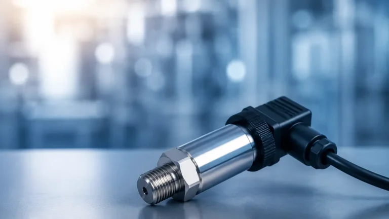
RTDs, such as the common Pt100 sensor, operate on the principle that the electrical resistance of a metal increases as its temperature rises. These sensors offer the highest levels of accuracy and stability over time. In modern industrial heating, RTDs are the standard for digital integration, providing signals (such as 4-20mA or Hart protocol) to PLC systems. This data is often cross-referenced with level data found on the Main Page to calculate mass or volume corrections based on thermal expansion.
The Relationship Between Temperature and Level Measurement
In B2B industrial environments, a heater thermometer is often a companion to level measurement instruments. When a medium is heated, its density changes, which can significantly impact the accuracy of certain level measurement technologies.
1. Hydrostatic Pressure: If a tank is heated, the fluid expands and its density decreases. A hydrostatic level transmitter measuring the pressure at the bottom of the tank will indicate a lower level than actually exists unless the system is compensated with temperature data from a heater thermometer.
2. Radar and Ultrasonic Signals: While radar is generally less affected by temperature than ultrasonic sensors, extreme heat can create vapor layers or turbulence. Monitoring the heater output ensures that the level meter is operating within its specified temperature range (typically up to 250°C or 450°C for specialized high-temp radar units).
3. Magnetic Level Gauges: These mechanical systems rely on a float. If the heater thermometer indicates a temperature that significantly lowers the fluid density, the float may no longer sit at the correct buoyancy level, requiring recalibration or a different float design.
Key Evaluation Criteria for Selection
Selecting the right heater thermometer requires an analysis of the process medium, the required accuracy, and the environmental conditions. Use the following table as a baseline for comparing common industrial options.
Selection Comparison Table
| Feature | Bimetallic Dial | Gas-Actuated | RTD (Pt100) | Thermocouple (Type K) |
| :— | :— | :— | :— | :— |
| Accuracy | ±1% to 2% of span | ±1% of span | ±0.1% to 0.5% | ±0.5% to 0.75% |
| Temp Range | -70°C to 500°C | -200°C to 700°C | -200°C to 600°C | -200°C to 1200°C+ |
| Response Time | Slow | Moderate | Fast | Very Fast |
| Power Required | No | No | Yes | Yes (Low Voltage) |
| Distance | Local only | Up to 30m (Capillary) | Long distance (Wiring) | Long distance (Wiring) |
| Cost | Low | Moderate | High | Moderate |
Installation Considerations
Proper installation is as important as instrument selection. A thermometer that is incorrectly placed will provide "dead zone" readings that do not reflect the actual state of the process.
Thermowell Integration
In most industrial heating applications, a heater thermometer should never be in direct contact with the process fluid if the fluid is corrosive, under high pressure, or if the system cannot be shut down for maintenance. A thermowell—a solid-metal bar-stock sleeve—is installed into the pipe or tank. The thermometer probe is then inserted into the thermowell. This allows for the removal of the instrument without draining the system. It is vital to use a thermal transfer compound inside the thermowell to ensure there is no air gap, which would otherwise lag the response time.
Insertion Depth
For accurate readings, the sensing element must be fully immersed in the moving stream of the fluid. A general rule of thumb is an insertion length of at least 10 times the diameter of the thermowell for liquids and 15 to 20 times for gases. In small pipes, the thermometer should be installed at an elbow or angled against the flow to ensure sufficient immersion.
Vibration and Environment
Heaters associated with pumps or high-pressure steam often generate significant vibration. In these cases, liquid-filled (glycerin or silicone) dial thermometers should be used to dampen the movement of the pointer and protect the internal mechanism from wear. For digital sensors, ensure the junction box has an appropriate IP rating (IP65 or higher) to protect against moisture and dust.
Common Risks and Limitations
While heater thermometers are generally reliable, certain factors can lead to measurement failure:
* Thermal Lag: In thick-walled thermowells or systems with high-viscosity fluids, the thermometer may take several minutes to register a change in temperature. This can be dangerous in runaway heating scenarios.
* Calibration Drift: Over time, mechanical springs can lose tension and RTD elements can oxidize. Regular calibration against a NIST-traceable standard is required, typically every 6 to 12 months.
* Scale Buildup: In water treatment or chemical processing, calcium or process residue can build up on the outside of the thermowell. This acts as an insulator, causing the thermometer to read lower than the actual process temperature.
* Ambient Temperature Interference: If a dial thermometer has a long external stem exposed to very cold ambient air, heat may be conducted away from the sensor, leading to a lower-than-actual reading (stem conduction error).
Frequently Asked Questions (FAQs)
Q: Can I use a standard thermometer for a high-pressure heater?
A: No. You must use a thermometer paired with a high-pressure rated thermowell. The thermowell is designed to withstand the system pressure, while the thermometer only measures the heat transferred through the well walls.
Q: What is the difference between a heater thermometer and a temperature transmitter?
A: A thermometer usually refers to the local sensing element or dial gauge. A transmitter is a device that converts the signal from a sensor (like an RTD) into a standardized 4-20mA signal for remote monitoring and control.
Q: How do I know if my thermometer has failed?
A: Common signs include a "stuck" pointer on analog gauges, erratic digital readings (jumping values), or a reading that remains at the maximum or minimum of the scale (indicating a short or open circuit in electronic sensors).
Q: Why is my thermometer reading different from my level meter's temperature probe?
A: Stratification often occurs in large tanks. The heater thermometer may be located near the heating element (reading higher), while the level meter's probe might be located higher up in the tank where the fluid is cooler. Always verify the mounting locations.
Conclusion
A heater thermometer is a fundamental component in any industrial thermal process. By selecting the appropriate measurement principle—whether it be a simple bimetallic dial for local checks or a high-precision RTD for automated control—operators can ensure safety and optimize fuel or power consumption. When integrated with reliable level measurement solutions, such as those detailed on the Welk Main Page, temperature data becomes a powerful tool for comprehensive process automation and accurate inventory management. Before finalizing a purchase, always confirm the chemical compatibility of the thermowell material and the required response time for your specific heating application.