Injection Molding Flow Meter
Injection Molding Flow Meter
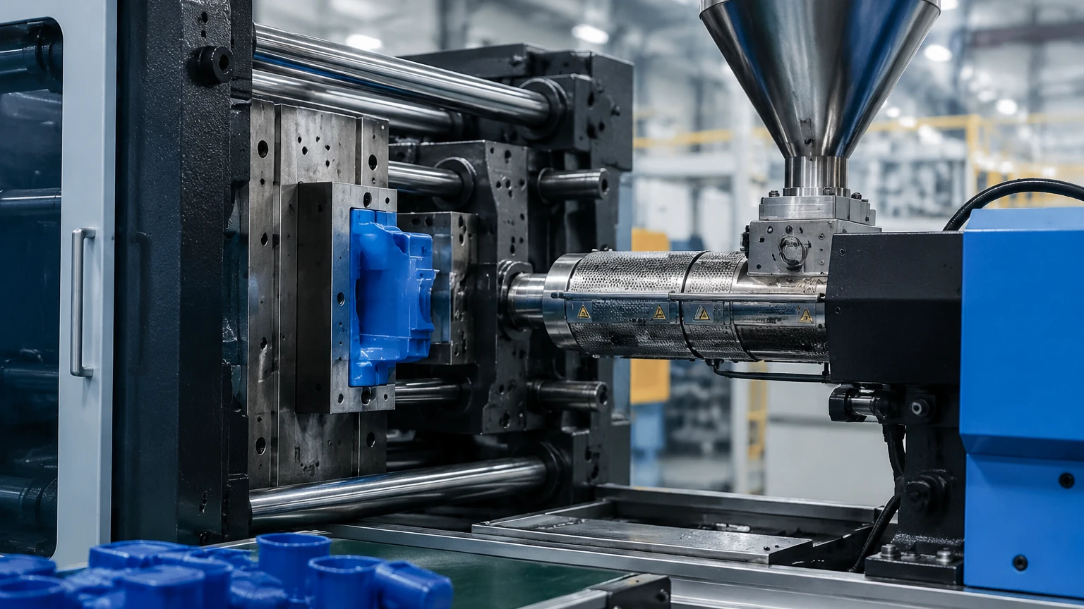
In the precision-driven world of plastic injection molding, thermal management is a critical factor that determines part quality, cycle efficiency, and overall production costs. The injection molding flow meter serves as a vital diagnostic and control tool within the cooling circuits of the mold. By monitoring the flow rate and temperature of the cooling media—typically water or a water-glycol mix—manufacturers can ensure that heat is removed consistently from the molten polymer. This article explores the technical principles, selection criteria, and installation best practices for flow meters in injection molding applications.
Measurement Principles for Cooling Circuits
Before selecting an injection molding flow meter, it is essential to understand the physical principles that govern how these devices quantify fluid movement. In industrial cooling applications, four primary technologies are commonly employed.
Variable Area (Rotameters)
Variable area meters operate on the principle of buoyancy and pressure drop. A float is housed within a tapered tube. as fluid flows upward, the float rises until the upward force of the fluid equals the weight of the float. The position of the float corresponds to a specific flow rate on a graduated scale. These are often used for manual monitoring on cooling manifolds due to their simplicity and lack of power requirements.
Turbine and Paddlewheel Meters
These mechanical meters utilize a rotor or paddlewheel placed in the flow stream. The velocity of the fluid causes the rotor to spin at a proportional rate. Sensors (often Hall-effect or inductive) count the rotations to calculate the volumetric flow. These are valued for their relatively high accuracy in clean water applications but can be susceptible to mechanical wear over time.
Ultrasonic (Transit-Time) Measurement
Ultrasonic flow meters represent a non-invasive solution. They use transducers to send and receive ultrasonic pulses through the fluid. The "transit-time" principle relies on the fact that sound waves traveling with the flow move faster than those traveling against it. The difference in time is directly proportional to the fluid velocity. Because they have no moving parts, they are highly resistant to fouling.
Electromagnetic (Magmeters)
Electromagnetic meters work based on Faraday’s Law of Induction. As a conductive liquid (like cooling water) moves through a magnetic field generated by the meter, it creates a voltage proportional to its velocity. These meters offer no obstruction to the flow, resulting in zero pressure drop, which is ideal for maintaining high-pressure cooling circuits.
Types of Flow Meters in Injection Molding
While various technologies exist, the specific demands of the injection molding environment—characterized by rapid cycles, high temperatures, and potential chemical additives—narrow the choices to a few standard configurations.
1. Manifold-Integrated Mechanical Meters: Often found on "Water-Reg" units, these provide visual confirmation of flow for each individual cooling channel. They are essential for identifying blocked lines or scale buildup.
2. Electronic Digital Flow Meters: These provide real-time data to the machine's PLC (Programmable Logic Controller). They allow for automated alarms if flow drops below a specific threshold (e.g., 5 liters per minute), preventing the mold from overheating and causing part deformation.
3. Vortex Shedding Flow Meters: These utilize a "bluff body" placed in the flow path to create vortices. The frequency of these vortices is proportional to the flow velocity. They are robust and can handle higher temperatures (up to 150°C or 302°F) often found in high-performance engineering plastics molding.
For engineers looking for comprehensive measurement solutions across their facility, including cooling water reservoir management, reviewing industrial options on the Main Page of specialized instrument providers like Welk can provide broader context on integrating flow and level data.
Selection Criteria and Practical Comparison
Choosing the right injection molding flow meter requires balancing accuracy requirements against budget and maintenance capabilities. The following table provides a comparison of common technologies used in mold cooling.
| Technology | Accuracy | Pressure Drop | Maintenance | Ideal Application |
| :— | :— | :— | :— | :— |
| Variable Area | ±5% to 10% | Moderate | Low | Manual manifold monitoring |
| Turbine | ±1% to 2% | High | Moderate | High-precision cooling control |
| Ultrasonic | ±1% to 3% | None | Very Low | Retrofitting without pipe cutting |
| Electromagnetic | ±0.5% to 1% | None | Low | Conductive fluids, high-volume lines |
| Vortex | ±1% to 2% | Moderate | Low | High-temperature oil or water |
Key Evaluation Factors
* Fluid Compatibility: Ensure the meter materials (e.g., brass, stainless steel, or specialized plastics) are compatible with the cooling media, especially if anti-corrosion or anti-freeze chemicals are used.
* Temperature Range: Standard cooling water may be 15°C to 30°C (59°F to 86°F), but specialized molds may require pressurized water at 120°C (248°F) or hot oil at 200°C+ (392°F+).
* Pressure Rating: The meter must withstand the maximum pump pressure of the Thermolator or cooling tower system, typically ranging from 4 to 10 bar (58 to 145 psi).
Installation Considerations
Proper installation is paramount to achieving accurate readings. An incorrectly installed injection molding flow meter will provide erratic data, leading to false alarms or undetected cooling failures.
Straight Pipe Requirements
Most flow meters require a specific length of straight pipe before (upstream) and after (downstream) the sensor to stabilize the flow profile. A common rule of thumb is "10D and 5D"—meaning a straight run of 10 times the pipe diameter before the meter and 5 times the diameter after it. This minimizes turbulence caused by elbows, valves, or pumps.
Orientation and Air Pockets
* Horizontal vs. Vertical: Mechanical and electromagnetic meters often perform best in vertical pipes with upward flow. This ensures the pipe is always full and prevents air bubbles from being trapped at the sensor head.
* Avoid High Points: Never install a flow meter at the highest point of a cooling circuit, as air pockets naturally migrate to these areas, which can cause ultrasonic and electromagnetic meters to fail or read inaccurately.
Integration with Level Measurement
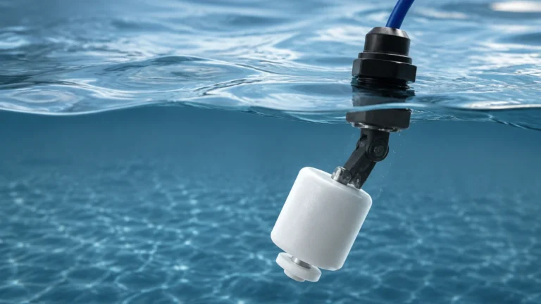
In many injection molding facilities, flow monitoring is only half of the equation. The cooling water is often stored in a central tank or reservoir. Maintaining a consistent level in these tanks is crucial to prevent pump cavitation. Welk provides a range of level measurement instruments, such as ultrasonic level sensors and radar level meters, that complement flow monitoring systems to ensure the entire cooling utility remains operational.
Limitations and Common Risks
While an injection molding flow meter is a robust tool, it is not without limitations. Understanding these risks helps in developing a proactive maintenance strategy.
1. Scaling and Fouling: In open-loop cooling towers, calcium and mineral deposits (scale) can build up inside the meter. This is particularly problematic for turbine meters, where scale can seize the rotor, and for variable area meters, where it can obscure the visual scale.
2. Viscosity Changes: If the cooling system uses a high concentration of glycol, the fluid's viscosity increases. Mechanical meters calibrated for pure water will require a correction factor, or the readings will be significantly off.
3. Electrical Noise: Electronic flow meters, particularly electromagnetic types, can be affected by electromagnetic interference (EMI) from the high-power motors and heaters found on injection molding machines. Shielded cabling and proper grounding are mandatory.
Frequently Asked Questions (FAQ)
Q: How often should I calibrate my injection molding flow meter?
A: For standard production, an annual calibration check is recommended. However, if you are molding high-precision medical or automotive components, semi-annual validation may be required to meet quality standards.
Q: Can I use a flow meter to detect leaks in the mold?
A: Yes. By comparing the flow rate at the inlet of the mold to the flow rate at the outlet, a differential flow system can detect internal leaks (cracked cooling channels) or external hose failures immediately.
Q: What is the difference between GPM and LPM in these meters?
A: GPM stands for Gallons Per Minute (Imperial), while LPM stands for Liters Per Minute (Metric). Most modern digital meters allow the user to toggle between these units in the settings menu. 1 GPM is approximately 3.785 LPM.
Q: Why is my ultrasonic flow meter giving a "No Signal" error?
A: This is usually caused by an empty pipe, excessive aeration in the water, or a lack of acoustic coupling gel between the transducers and the pipe surface.
Conclusion
Implementing a robust injection molding flow meter system is a fundamental step toward achieving scientific molding goals. By moving from "visual estimation" to "data-driven monitoring," molding shops can reduce scrap rates, optimize cycle times, and protect expensive tooling from thermal stress. Whether using simple mechanical indicators or advanced digital electromagnetic sensors, the key lies in matching the technology to the specific thermal demands of the process. For those managing broader industrial fluid systems, integrating these flow insights with reliable level measurement solutions from manufacturers like Welk ensures a holistic approach to process automation and reliability.