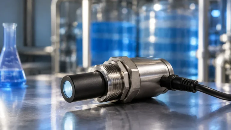
Rtd Assembly
Rtd Assembly
In the realm of industrial process control, temperature is one of the most frequently measured physical parameters. Among the various sensors available, the Resistance Temperature Detector (RTD) is widely regarded as the gold standard for accuracy, stability, and repeatability. An RTD assembly is not merely a sensor; it is a complete engineered package designed to protect the sensing element from harsh process conditions while ensuring rapid and precise thermal response.
For engineers and technicians involved in industrial automation, understanding the nuances of an RTD assembly is essential for optimizing system performance. Whether integrated into complex level measurement systems or used as standalone temperature monitors, these assemblies provide the reliable data necessary for safety and efficiency. To explore a wide range of industrial measurement instruments, including those used for level and process control, you can visit the Main Page of our product catalog.
Measurement Principles of RTDs
The operation of an RTD is based on a fundamental property of metals: electrical resistance increases as temperature increases. This phenomenon is known as the positive temperature coefficient (PTC).
The Resistance-Temperature Relationship
Most industrial RTDs utilize platinum (Pt) due to its chemical inertness, wide temperature range, and highly linear resistance-to-temperature relationship. The most common standard is the Pt100, which has a nominal resistance of 100 Ω at 0°C (32°F). The relationship is defined by the Callendar-Van Dusen equation, though for most practical purposes within a limited range, a linear coefficient of 0.00385 Ω/Ω/°C is used.
Sensing Element Types
There are two primary constructions for the sensing element within an RTD assembly:
1. Wire-Wound Elements: These consist of a fine platinum wire coiled around a ceramic or glass core. They offer superior accuracy and stability over a wide temperature range but are more susceptible to damage from high vibration.
2. Thin-Film Elements: These are created by depositing a thin layer of platinum onto a ceramic substrate using vacuum evaporation or sputtering. They are more rugged, cost-effective, and resistant to vibration, making them the standard choice for most modern industrial applications.
Components of a Complete RTD Assembly
A professional-grade RTD assembly consists of several critical components, each serving a specific function to ensure the longevity and accuracy of the sensor.
1. The Sensing Element
As discussed, this is the heart of the assembly, typically a Pt100 or Pt1000 element. It is responsible for the actual transduction of thermal energy into electrical resistance.
2. Protective Sheath (Probe)
The sensing element is encapsulated in a metal tube, usually made of Stainless Steel 316 (SS316) or high-nickel alloys like Inconel. The sheath protects the element from moisture, pressure, and physical impact. Standard diameters range from 3 mm (0.12 in) to 12 mm (0.47 in).
3. Internal Insulation
The space between the element and the sheath is filled with a compacted mineral insulation, typically Magnesium Oxide (MgO). This provides excellent thermal conductivity while maintaining high electrical insulation resistance between the sensor and the outer sheath.
4. Connection Head
The connection head is the enclosure at the top of the assembly where the internal wires connect to the external field wiring. These are available in various materials, including:
* Aluminum: Lightweight and durable for general purpose.
* Stainless Steel: For corrosive environments or food-grade applications.
* Plastic/Nylon: For cost-sensitive, non-hazardous areas.
* Explosion-Proof: Specifically designed to contain internal sparks in hazardous zones.
5. Process Connection
This is the mechanism used to mount the RTD assembly to a tank or pipe. Common options include NPT or BSP threaded fittings, flanges, or sanitary tri-clamp fittings for the pharmaceutical and food industries.
RTD Wiring Configurations
One of the most critical decisions during the selection of an RTD assembly is the wiring configuration. Since the RTD measures resistance, the resistance of the lead wires themselves can introduce errors if not properly compensated.
| Configuration | Description | Accuracy | Application |
| :— | :— | :— | :— |
| 2-Wire | Two leads connect to the element. Lead resistance is added directly to the sensor resistance. | Low | Short distances, low accuracy requirements. |
| 3-Wire | Three leads are used. The third wire allows the controller to measure and subtract lead resistance. | High | Standard industrial practice; balances cost and accuracy. |
| 4-Wire | Four leads provide a true Kelvin bridge measurement, completely eliminating lead resistance impact. | Highest | Laboratory standards and high-precision calibration. |
In most industrial environments, the 3-wire configuration is the preferred choice as it provides sufficient accuracy for process control while using standard multi-core cabling.
Selection Criteria for Industrial RTD Assemblies
When selecting an RTD assembly for a specific application, engineers must evaluate several factors to ensure compatibility and performance.
Temperature Range
Standard RTDs are generally rated for -200°C to +600°C (-328°F to +1112°F). However, the specific construction of the assembly (insulation, sheath material, and lead wire type) may limit this range. For temperatures exceeding 600°C, thermocouples are often preferred.
Accuracy Classes (IEC 60751)
RTDs are categorized into accuracy classes based on their tolerance at specific temperatures:
* Class B: ±(0.30 + 0.005|t|) °C
* Class A: ±(0.15 + 0.002|t|) °C
* 1/3 DIN: ±(0.10 + 0.0017|t|) °C
Response Time
The time it takes for the sensor to reach 63.2% of a step change in temperature is known as the time constant (T63). This is influenced by the sheath diameter and the presence of a thermowell. Smaller diameters react faster but are less mechanically robust.
Environmental Conditions
If the process involves corrosive chemicals, high-velocity steam, or extreme pressures, the RTD assembly must be paired with a thermowell. A thermowell is a pressure-tight receptacle that protects the sensor and allows for its removal without draining the process vessel.

Installation Considerations and Best Practices
Proper installation is vital to obtaining accurate temperature readings and extending the life of the RTD assembly.
Immersion Depth
To avoid errors caused by heat conduction along the sheath (stem conduction), the sensor must be immersed deep enough into the process. A general rule of thumb is an immersion depth of at least 10 times the outer diameter of the protection tube. For example, a 6 mm probe should be immersed at least 60 mm (2.36 in) into the fluid.
Orientation in Pipes
In piping systems, the RTD assembly should ideally be installed against the flow or in an elbow to maximize turbulence and thermal contact. If installed perpendicular to the flow, ensure the probe reaches the center of the pipe where the velocity and temperature profile are most representative.
Vibration Mitigation
In high-vibration environments, such as near pumps or compressors, spring-loaded RTD assemblies should be used. These maintain constant contact between the sensor tip and the bottom of the thermowell, reducing mechanical stress and improving thermal transfer.
Limitations of RTD Assemblies
While RTDs are highly versatile, they are not suitable for every application. Limitations include:
* Self-Heating: The current used to measure resistance generates a small amount of heat within the element, potentially skewing the reading if the excitation current is too high.
* Fragility: Thin-film elements can be damaged by extreme mechanical shock.
* Cost: RTD assemblies are generally more expensive than thermocouples.
* Upper Temperature Limit: They cannot reach the extreme temperatures (up to 1700°C) handled by Type R or S thermocouples.
The Role of RTDs in Level Measurement
In many industrial applications, temperature and level measurement go hand-in-hand. For instance, in hydrostatic level measurement, the density of a liquid changes with temperature. An RTD assembly provides the temperature data required for the control system to calculate the true level accurately. Similarly, in radar level measurement, temperature monitoring of the vapor space can be critical for certain gas-phase compensation algorithms.
For professional-grade level sensors that integrate seamlessly with temperature monitoring systems, visit the Main Page to view our latest technical specifications.
Frequently Asked Questions (FAQ)
Q: How often should an RTD assembly be calibrated?
A: In stable processes, annual calibration is standard. However, in applications with high vibration or thermal cycling, semi-annual checks are recommended to monitor for sensor drift.
Q: Can I use a 2-wire RTD with a 3-wire controller?
A: Yes, by jumping the two common terminals at the controller, but you will lose the lead-wire compensation, resulting in lower accuracy.
Q: What is the difference between PT100 and PT1000?
A: A PT100 has 100 Ω at 0°C, while a PT1000 has 1000 Ω. PT1000 sensors are better for 2-wire configurations because the lead wire resistance is a much smaller percentage of the total resistance, reducing error.
Q: Why would I choose a spring-loaded RTD?
A: Spring-loading ensures the sensor tip is always pressed against the bottom of the thermowell. This optimizes heat transfer and protects the element from vibration damage by preventing it from rattling inside the well.
By carefully considering the construction, wiring, and installation of the RTD assembly, process engineers can ensure reliable temperature data that forms the backbone of safe and efficient industrial operations.