How to Calibrate a Pressure Transmitter
How to Calibrate a Pressure Transmitter
In industrial process control, the accuracy of level and pressure measurements is fundamental to safety, efficiency, and product quality. Pressure transmitters serve as the primary sensory organs for many automated systems, particularly in hydrostatic level measurement. However, like all precision instruments, these devices are subject to drift over time due to environmental factors, mechanical wear, or electronic aging. Understanding how to calibrate a pressure transmitter is a critical skill for instrument technicians and process engineers to ensure the integrity of the data being fed into PLC or DCS systems.
Calibration is the process of comparing a device under test (DUT) against a traceable reference standard and adjusting the device so that its output accurately reflects the input within a specified tolerance. For a pressure transmitter, this typically involves applying a known pressure and verifying that the resulting electrical signal—usually 4-20 mA—corresponds to the expected values.
Measurement Principles and Hydrostatic Level
Before diving into the calibration procedure, it is essential to understand the underlying physics. In the context of level measurement, pressure transmitters often operate on the principle of hydrostatic pressure. This principle states that the pressure exerted by a liquid column at rest is directly proportional to its height and the density of the fluid.
The formula is expressed as:
P = ρ × g × h
Where:
* P is the hydrostatic pressure.
* ρ (rho) is the density of the liquid (kg/m³).
* g is the gravitational constant (approximately 9.81 m/s²).
* h is the height of the liquid column (m).
In a typical setup, a pressure transmitter is mounted at the bottom of a tank. As the liquid level rises, the pressure on the diaphragm increases. The transmitter converts this physical force into an analog or digital signal. For example, if a tank is 10 meters high and filled with water (density ~1000 kg/m³), the pressure at the bottom would be approximately 98.1 kPa (0.98 bar or 14.2 psi). Calibration ensures that when the transmitter senses 98.1 kPa, it outputs exactly 20 mA (representing 100% volume).
For those seeking specific hardware to implement these measurements, you can Review product options and application support on the Welk Main Page to find instruments tailored to various industrial densities and tank geometries.
Essential Tools for Calibration
To perform a professional calibration, several specialized tools are required to ensure traceability and precision:
1. Pressure Source: This can be a pneumatic or hydraulic hand pump, a deadweight tester, or a nitrogen cylinder with a precision regulator.
2. Reference Standard (Master Gauge): A digital pressure calibrator or a high-accuracy test gauge that has been recently certified and is at least four times more accurate than the transmitter being calibrated.
3. Multimeter or Loop Calibrator: Used to measure the 4-20 mA output signal.
4. Power Supply: Usually 24V DC to power the transmitter loop.
5. HART Communicator: For smart transmitters, a HART (Highway Addressable Remote Transducer) modem or handheld terminal is necessary to adjust digital parameters.
6. Resistor: A 250-ohm resistor is often required if using a HART communicator without a built-in load.
Step-by-Step Guide: How to Calibrate a Pressure Transmitter
The following procedure outlines a standard five-point calibration check (0%, 25%, 50%, 75%, and 100% of the range).
1. Preparation and Safety
Before starting, isolate the transmitter from the process. Close the block valves and open the vent valves to release any trapped pressure. Ensure the environment is stable; extreme temperature fluctuations can affect the accuracy of the calibration. Clean the transmitter's diaphragm if it has been in contact with corrosive or viscous media.
2. The Bench Setup
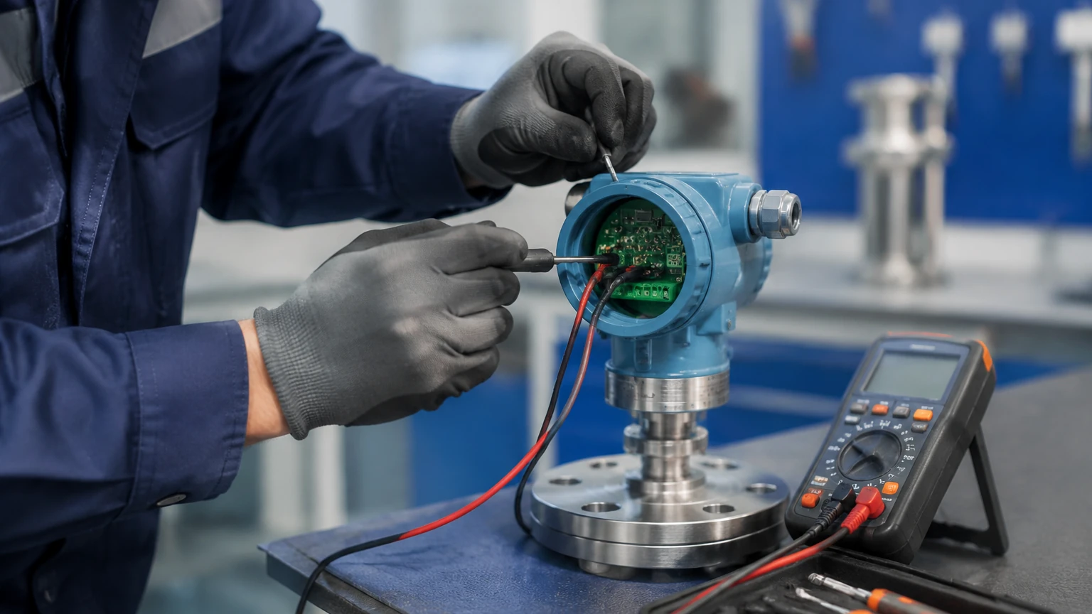
Connect the pressure source to the high-pressure side of the transmitter. If it is a differential pressure (DP) transmitter, ensure the low-pressure side is vented to the atmosphere (unless performing a static pressure test). Connect the multimeter in series with the power supply and the transmitter to measure the current loop.
3. Zero Adjustment (The Lower Range Value – LRV)
With the transmitter vented to the atmosphere (0 kPa applied), check the output. It should read exactly 4.000 mA. If the reading is outside the allowable tolerance (e.g., 4.01 mA), use the "Zero" adjustment screw on analog units or the "Zero Trim" function on a HART communicator to bring it back to 4.000 mA.
4. Span Adjustment (The Upper Range Value – URV)
Apply the maximum pressure corresponding to the 100% mark of your process (e.g., 100 kPa). The output should read exactly 20.000 mA. If it does not, adjust the "Span" screw or use the HART "Sensor Trim" function. Note that adjusting the span may slightly shift the zero point, so it is often necessary to repeat steps 3 and 4 until both points are accurate.
5. Linearity and Hysteresis Check
Once the zero and span are set, perform a full five-point check:
* 0%: 4 mA
* 25%: 8 mA
* 50%: 12 mA
* 75%: 16 mA
* 100%: 20 mA
Record the readings both while increasing pressure (upscale) and decreasing pressure (downscale). The difference between the upscale and downscale readings at the same point is the hysteresis. If the errors exceed the manufacturer’s specifications (typically 0.075% to 0.25% of span), the transmitter may require repair or replacement.
Practical Selection Table for Pressure Transmitters
When selecting a transmitter for a specific application, consider the following technical parameters:
| Feature | Gauge Pressure | Absolute Pressure | Differential Pressure (DP) |
| :— | :— | :— | :— |
| Reference Point | Atmospheric Pressure | Full Vacuum | Difference between two points |
| Common Use | Open tank level, pump discharge | Distillation columns, vacuum tanks | Closed/Pressurized tanks, flow |
| Calibration Complexity | Low | Medium (requires vacuum source) | High (requires manifold handling) |
| Welk Recommendation | Standard industrial liquids | Low-pressure gas/vapor | Pressurized chemical reactors |
Installation Considerations
Proper installation is as important as accurate calibration. Even a perfectly calibrated transmitter will provide false data if installed incorrectly.
* Impulse Lines: Keep impulse lines as short as possible to reduce lag and potential for clogs. For gas applications, the transmitter should be mounted above the tapping point to allow condensate to drain back. For liquid applications, mount it below the tapping point to allow gas bubbles to escape.
* Mounting Position: Transmitters are sensitive to gravity. If a transmitter is calibrated in a horizontal position but installed vertically, a zero shift may occur. Always perform a final "Zero Trim" once the unit is in its final mounting orientation.
* Environmental Protection: Use sunshades or heat tracing if the transmitter is exposed to extreme temperatures. Standard operating ranges are usually between -40°C and +85°C (-40°F to 185°F).
Limitations and Common Risks
While learning how to calibrate a pressure transmitter is straightforward, several factors can compromise the process:
* Ambient Temperature Drift: Most transmitters have internal temperature compensation, but extreme shifts during calibration can cause errors. Always allow the device to reach thermal equilibrium with the calibration environment.
* Power Supply Fluctuations: Ensure the 24V DC source is stable. Noise on the power line can cause the mA output to fluctuate, making it difficult to get a steady reading.
* Overpressure Damage: Never apply pressure exceeding the Maximum Working Pressure (MWP) of the sensor. This can permanently deform the diaphragm, leading to non-linear errors that cannot be calibrated out.
* Contamination: Ensure the calibration fluid (air, oil, or water) is clean. Debris in the calibration pump can enter the transmitter sensor and cause blockages or damage.
Frequently Asked Questions (FAQ)
Q: How often should I calibrate my pressure transmitter?
A: For most industrial applications, an annual calibration check is standard. However, in critical safety loops or high-vibration environments, semi-annual or quarterly checks may be required. If the process involves corrosive media, more frequent inspections are advised.
Q: What is the difference between a "Re-range" and a "Calibration"?
A: Re-ranging involves changing the Upper and Lower Range Values (e.g., changing a 0-10 bar range to 0-5 bar) via software without applying pressure. Calibration involves applying a physical pressure to verify and adjust the actual sensor performance.
Q: Can I calibrate a transmitter while it is still in the process line?
A: Yes, this is known as a "Field Calibration." It requires a 3-way or 5-way valve manifold to isolate the transmitter from the process and vent it to the calibration equipment. Field calibration is preferred as it accounts for the actual mounting position and environmental conditions.
Q: How do I handle density changes in level measurement?
A: If the liquid density (Specific Gravity) changes, the hydrostatic pressure will change even if the level remains the same. In these cases, you must recalculate the URV based on the new density or use a transmitter with built-in temperature/density compensation.
For engineers designing new systems or replacing aging infrastructure, selecting the right technology is the first step toward reducing calibration frequency. Welk offers a range of radar and ultrasonic solutions that often require less maintenance than traditional pressure-based systems in specific applications. You can explore these alternatives on the Main Page.
By following these technical guidelines and maintaining a rigorous calibration schedule, facilities can ensure that their level measurement systems remain accurate, reliable, and compliant with industry standards.