Sensor Level
Sensor Level
In industrial process control, the term "sensor level" refers to the precise measurement and monitoring of the height of liquids, slurries, or granular solids within a vessel or container. Accurate level sensing is critical for inventory management, process efficiency, and safety across industries such as water treatment, chemical processing, oil and gas, and food production. Selecting the appropriate technology requires a deep understanding of the physical principles governing different measurement methods and the environmental factors that can influence their performance.
As a professional manufacturer, Welk provides a comprehensive range of industrial level measurement instruments, including radar level meters, ultrasonic sensors, and hydrostatic transmitters. This guide explores the core principles of level measurement, practical selection criteria, and installation best practices for engineering professionals.
Core Principles of Level Measurement
Level measurement technologies are generally categorized into two types: non-contact and contact. Each relies on different physical properties of the medium and the environment to determine the sensor level.
1. Radar Level Measurement (Non-Contact)
Radar level meters utilize electromagnetic waves, typically in the microwave frequency range (e.g., 26 GHz or 80 GHz). The sensor emits a pulse toward the material surface, which reflects a portion of the energy back to the receiver. By measuring the time-of-flight (ToF) or the frequency shift (in FMCW radar), the device calculates the distance to the product.
* Advantages: Immune to dust, temperature fluctuations, and pressure changes. High-frequency 80 GHz radar offers a narrow beam angle, which is ideal for narrow tanks or vessels with internal obstructions.
* Limitations: Highly dependent on the dielectric constant (Dk) of the material. Materials with a low Dk (like some oils) reflect less energy, requiring more sensitive electronics.
2. Ultrasonic Level Measurement (Non-Contact)
Ultrasonic sensors function by emitting high-frequency sound waves. These waves travel through the air, hit the surface of the medium, and return to the transducer. The sensor level is determined by the time it takes for the sound pulse to return.
* Advantages: Cost-effective for water and wastewater applications. No contact with the media ensures longevity in corrosive environments.
* Limitations: Sound speed is affected by air temperature, requiring temperature compensation. Ultrasonic waves can be absorbed by heavy foam or scattered by heavy dust and turbulence.
3. Hydrostatic Level Measurement (Contact)
Hydrostatic transmitters measure the pressure exerted by a liquid column at a specific point. Based on the formula $P = \rho \cdot g \cdot h$ (where $P$ is pressure, $\rho$ is density, $g$ is gravity, and $h$ is height), the sensor level can be accurately derived if the density of the liquid remains constant.
* Advantages: Simple installation (submersible or flange-mounted) and very reliable for vented tanks.
* Limitations: Changes in liquid density or pressurized tank environments (without differential pressure compensation) will result in measurement errors.
4. Magnetic Level Gauges and Switches (Contact)
Magnetic level gauges use a float containing a permanent magnet that moves with the liquid level. This magnet interacts with an external indicator or a reed switch array. Level switches, on the other hand, provide point-level detection (high or low alarms) rather than continuous measurement.
Technology Selection Criteria
Choosing the right sensor level technology involves evaluating the physical state of the media, the vessel geometry, and the required accuracy. The following table provides a comparison of common technologies used in industrial automation.
| Technology | Typical Accuracy | Max Range | Media Type | Key Limitation |
| :— | :— | :— | :— | :— |
| Radar (80 GHz) | ±1 mm | 120 m | Liquids/Solids | Low dielectric materials |
| Ultrasonic | ±0.25% of range | 15–30 m | Liquids/Slurries | Foam, vacuum, high temp |
| Hydrostatic | ±0.1% to 0.5% | 200 m (H2O) | Liquids | Changing density |
| Magnetic Gauge | ±5 mm | 6 m | Clean Liquids | High viscosity, coating |
| Capacitance | ±1% | 10 m | Liquids/Solids | Coating on probe |
For a detailed look at specific instrument specifications and to explore customized OEM/ODM options, you can visit our Main Page for technical documentation and product support.
Practical Engineering Considerations
Media Characteristics
* Dielectric Constant: For radar sensors, the Dk value determines the strength of the reflected signal. Water has a high Dk (~80), making it easy to measure, while hydrocarbons often have Dk values between 1.8 and 4.0, requiring specialized high-sensitivity radar.
* Viscosity and Coating: In contact measurements, such as magnetic gauges or tuning fork switches, highly viscous liquids can cause the float to stick or the sensor to give false readings due to material buildup.
* Corrosiveness: Corrosive chemicals like sulfuric acid require sensors made from compatible materials such as PTFE, PVDF, or high-grade stainless steel.
Environmental Factors
* Vessel Internal Obstructions: Agitators, heating coils, and ladders can create false echoes for radar and ultrasonic sensors. Modern sensors use "false echo suppression" software to map out these reflections.
* Temperature and Pressure: Extreme temperatures (above 200°C) or high pressures (above 40 bar) often necessitate the use of radar or specialized magnetic gauges, as ultrasonic transducers and hydrostatic diaphragms have lower tolerance limits.
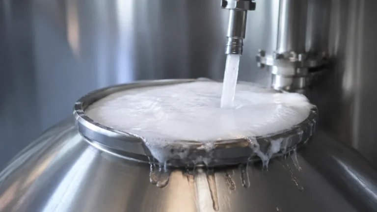
* Foam and Turbulence: Heavy foam can act as an insulator for ultrasonic waves. In these cases, radar or hydrostatic sensors are preferred. For turbulent surfaces, software averaging or the use of a stilling well can stabilize the reading.
Installation Best Practices
Correct installation is as vital as selecting the right technology. Failure to follow mounting guidelines often leads to signal loss or inaccurate data.
1. Avoid the "Dead Zone": Every non-contact sensor has a blocking distance (dead zone) near the transducer face where measurements are impossible. Ensure the maximum sensor level expected in the tank does not enter this zone.
2. Mounting Position: Sensors should generally not be mounted in the center of a domed tank, as this can concentrate reflected signals and cause interference. They should also be kept away from the fill stream to avoid false readings during tank loading.
3. Nozzle Height and Diameter: For radar and ultrasonic sensors, the nozzle should be as short and wide as possible to prevent the beam from hitting the nozzle walls, which creates "ringing" or parasitic reflections.
4. Alignment: For solids measurement, aiming the sensor at the angle of repose is necessary to ensure a sufficient return signal to the transducer.

Limitations and Challenges
While modern sensor level technology is advanced, certain boundaries remain:
* Vacuum Conditions: Ultrasonic waves cannot travel through a vacuum. In vacuum distillation or similar processes, radar (which uses electromagnetic waves) or hydrostatic sensors must be used.
* Vapor Layers: Heavy steam or chemical vapors can change the speed of sound, affecting ultrasonic accuracy. Radar is generally unaffected by vapors unless they are highly polar and at extremely high concentrations.
* Density Variations: If a hydrostatic sensor is calibrated for water (density 1000 kg/m³) but the process fluid changes to an oil (density 800 kg/m³), the reported level will be significantly lower than the actual level.
Frequently Asked Questions (FAQ)
Q: Can I use one sensor for both liquids and solids?
A: Some high-frequency radar sensors are versatile enough for both. However, solids measurement usually requires a higher power output and a narrower beam to handle the uneven surfaces and dust typical of silos.
Q: How often do level sensors need calibration?
A: This depends on the technology. Hydrostatic sensors may drift over time due to diaphragm fatigue and should be checked annually. Radar and ultrasonic sensors are generally more stable but should be verified if process conditions change significantly.
Q: What is the difference between 26 GHz and 80 GHz radar?
A: 80 GHz radar has a much smaller wavelength, allowing for a smaller antenna and a tighter beam angle (as low as 3 degrees). This makes it superior for avoiding internal tank obstructions and measuring through narrow nozzles.
Q: How do I measure level in a pressurized tank?
A: For pressurized tanks, hydrostatic measurement requires a differential pressure (DP) transmitter to subtract the headspace pressure from the total pressure at the bottom. Alternatively, radar or magnetic gauges are unaffected by tank pressure.
Conclusion
Achieving an accurate sensor level reading requires a balance between technology capability and application requirements. By understanding the physics of radar, ultrasonic, and hydrostatic measurement, engineers can select the most cost-effective and reliable solution for their specific process. Proper installation, including the consideration of dead zones and beam angles, ensures long-term operational success. For further technical assistance and to view our full range of industrial measurement solutions, please refer to the Main Page for comprehensive product specifications and application engineering support.