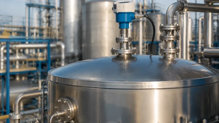
4 Level Transmitter
4 Level Transmitter
In modern industrial automation, the term "4 level transmitter" typically refers to instruments utilizing the 4-20mA analog signaling standard or 4-wire power configurations. These devices are the workhorses of process control, providing continuous level data to Programmable Logic Controllers (PLCs) and Distributed Control Systems (DCS). Selecting the correct transmitter requires a deep understanding of measurement physics, media characteristics, and environmental constraints.
This guide explores the engineering principles behind these transmitters, with a specific focus on high-precision technologies such as radar, and provides a framework for selecting the most reliable equipment for complex industrial applications.
1. Understanding Measurement Principles
Before selecting a 4 level transmitter, it is essential to understand the physical principles that govern different measurement technologies. Most industrial level transmitters fall into one of three categories: Time-of-Flight (ToF), Pressure-based, or Electromechanical.
Time-of-Flight (ToF) Principles
ToF instruments measure the time it takes for a signal to travel from the sensor to the liquid surface and back. This category includes:
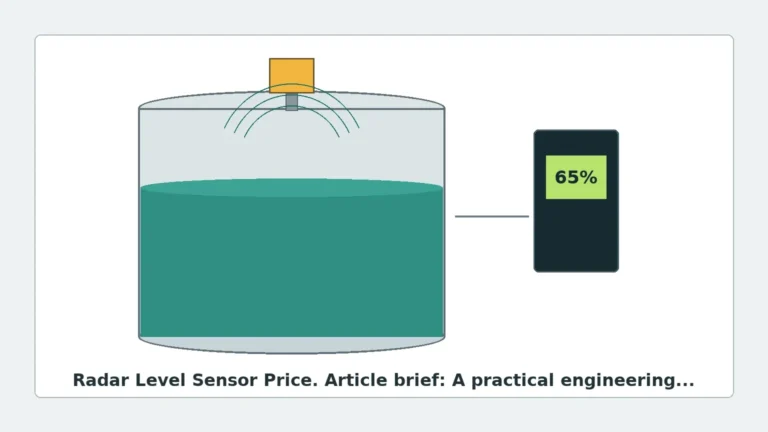
* Radar (Microwave): Uses high-frequency electromagnetic waves. Radar is largely unaffected by temperature, pressure, or vacuum conditions.
* Ultrasonic: Uses sound waves. While cost-effective, ultrasonic signals are sensitive to air temperature gradients, heavy vapors, and surface foam.
Hydrostatic Pressure
This principle measures the weight of the liquid column above the sensor. The pressure ($P$) is proportional to the height ($h$) of the liquid, the density ($
ho$), and gravity ($g$): $P =
ho gh$. These transmitters are highly reliable for vented tanks but require density compensation if the liquid composition changes.
Capacitance and Conductivity
These sensors detect changes in electrical properties. Capacitance transmitters measure the change in dielectric constant between two electrodes (or an electrode and the tank wall) as the level rises. These are often used for point-level detection or in highly conductive liquids.
2. The Role of Radar Level Meters in 4-20mA Systems
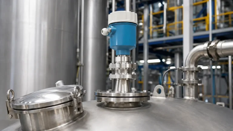
Among the various technologies, Radar Level Meters have become the preferred choice for high-accuracy industrial applications. They are inherently compatible with 4-20mA loops, often providing a digital HART (Highway Addressable Remote Transducer) signal superimposed on the analog current loop.
Frequency Modulated Continuous Wave (FMCW) vs. Pulse Radar
Modern radar transmitters generally use one of two methods:
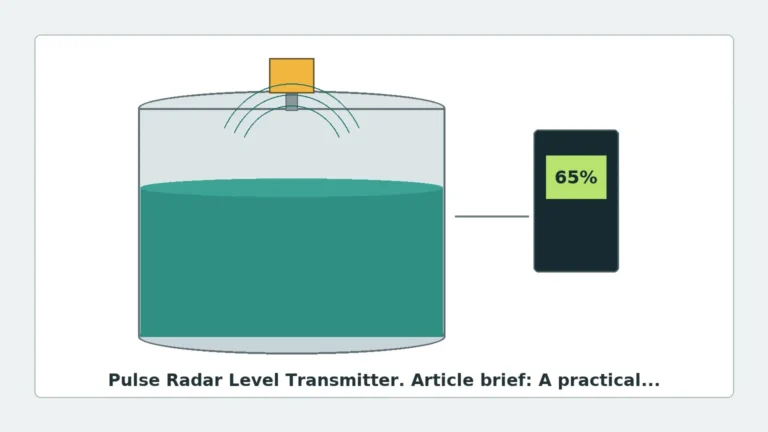
1. Pulse Radar: Sends a short microwave pulse and measures the time delay. It is energy-efficient and suitable for 2-wire (loop-powered) configurations.
2. FMCW Radar: Transmits a continuous signal with a varying frequency. The difference in frequency between the transmitted and received signal is proportional to the distance. FMCW offers much higher resolution and accuracy, particularly in low-dielectric media.
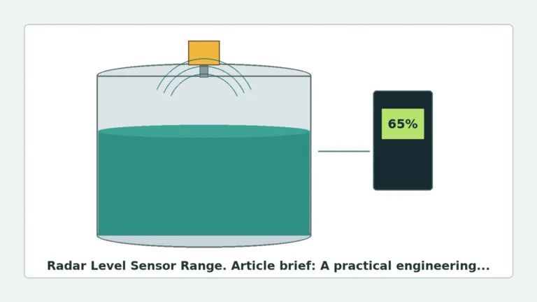
High-frequency radar (e.g., 80GHz) provides a narrow beam angle, which is critical for avoiding internal tank obstructions like agitators, heating coils, or ladders.
3. Technical Comparison: 2-Wire vs. 4-Wire Configurations
When specifying a 4 level transmitter, engineers must choose between 2-wire and 4-wire electrical architectures. This choice impacts the power budget available for the sensor and the complexity of the wiring.
| Feature | 2-Wire (Loop Powered) | 4-Wire (Separate Power) |
| :— | :— | :— |
| Wiring | 2 wires for both power and signal | 2 wires for power, 2 wires for signal |
| Power Supply | Typically 24V DC | 24V DC, 110V AC, or 220V AC |
| Power Consumption | Low (Limited by the 4mA floor) | Higher (Supports heaters, backlights) |
| Signal Output | 4-20mA / HART | 4-20mA, Modbus, Relay outputs |
| Application | Standard process tanks, remote sites | High-power sensors, complex displays |
4. Selection Criteria and Application Matrix
Choosing the right 4 level transmitter involves matching the technology to the specific media and vessel conditions. The following table provides a general selection framework for common industrial scenarios.
| Application | Recommended Technology | Key Benefit |
| :— | :— | :— |
| Corrosive Chemicals | Non-contact Radar (PTFE Lens) | No wetted metal parts; high resistance |
| Waste Water Sump | Ultrasonic or Hydrostatic | Cost-effective; handles turbulent surfaces |
| High-Pressure Steam | Guided Wave Radar (GWR) | Signal guided by probe; ignores steam |
| Oil/Water Interface | Guided Wave Radar | Detects multiple dielectric layers |
| Bulk Solids/Grain | 80GHz Radar | Penetrates dust; narrow beam for silos |
| Food & Beverage | Hydrostatic (Hygienic) | Flush diaphragms; CIP/SIP compatible |
5. Installation Best Practices and Constraints
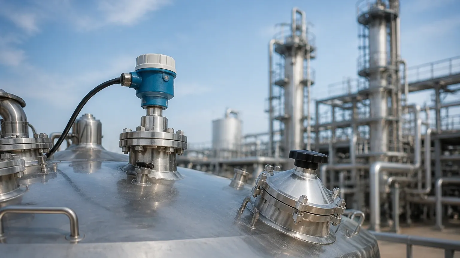
Even the most advanced radar level meters will fail to perform if installed incorrectly. Engineers must adhere to strict mounting guidelines to ensure signal integrity.
Nozzle Geometry
The mounting nozzle (standpipe) should be as short as possible. If a nozzle is too long or too narrow, the radar signal may reflect off the nozzle walls, creating a "ringing" effect that masks the true level of the liquid. For 80GHz transmitters, nozzle heights up to 500mm are often acceptable, but for lower frequency 26GHz units, shorter nozzles are required.
The "Dead Zone" (Blocking Distance)
Every 4 level transmitter has a minimum measurable distance, known as the dead zone or blocking distance, located immediately below the sensor face. If the liquid enters this zone, the device may report an error or a fixed maximum value. Typically, this range is between 50mm and 300mm depending on the technology.
Avoiding Obstructions
The signal beam (whether ultrasonic or radar) spreads as it travels. The "beam angle" defines the cone within which the signal remains strong. No internal structures (pipes, baffles, or agitators) should intersect this cone. If obstructions are unavoidable, many modern transmitters offer "false echo suppression" software to digitally ignore these static reflections.
Metric Installation Standards
* Flange Sizes: Common sizes include DN50, DN80, and DN100 (PN16/PN40 ratings).
* Threaded Connections: G1½" or NPT 1½" are standard for smaller vessels.
* Positioning: The sensor should ideally be placed at 1/6th to 1/4th of the tank diameter from the wall to avoid interference from wall reflections and the vortex created by central agitators.
6. Limitations and Application Risks
While a 4 level transmitter is highly versatile, certain environmental factors can introduce measurement errors or total signal loss.
1. Dielectric Constant ($\epsilon_r$): Radar depends on the media's ability to reflect microwaves. Hydrocarbons (oil, diesel) have low dielectric constants ($\epsilon_r < 2.5$), resulting in weaker reflections. In these cases, high-sensitivity FMCW radar or Guided Wave Radar is required.
2. Foam: Heavy, dense foam can absorb radar and ultrasonic signals. If a thick foam layer is present, a hydrostatic transmitter or a displacement-type sensor may be more reliable.
3. Vapor and Condensation: While radar is immune to most vapors, heavy condensation on the sensor face can attenuate the signal. Transmitters with PTFE lens covers or "drip-off" antenna designs are recommended for high-humidity environments.
4. Turbulence: Rapidly changing surface levels or heavy agitation can scatter the signal. Software damping and signal averaging are used to stabilize the 4-20mA output in these conditions.
7. Buyer Confirmation Checklist
When procuring a 4 level transmitter from international manufacturers, technical buyers should confirm the following data points to ensure compatibility:
* Media Properties: What is the dielectric constant? Is the liquid corrosive, viscous, or prone to crystallization?
* Process Conditions: What are the maximum and minimum operating temperatures and pressures? (Standard units often handle -40°C to +150°C; specialized units go higher).
* Tank Geometry: Provide the total height, nozzle diameter, and a list of internal obstructions.
* Output Requirements: Is a standard 4-20mA signal sufficient, or is HART, Modbus, or Profibus required for integration?
* Certification: Does the site require ATEX/IECEx (Explosion-proof) or SIL2 (Safety Integrity Level) ratings?
8. Frequently Asked Questions (FAQ)
Q: Can a 4-20mA level transmitter be used in a vacuum?
A: Yes, if it is a radar or guided wave radar type. Ultrasonic transmitters cannot operate in a vacuum because sound waves require a medium (air/gas) to travel. Hydrostatic transmitters may require a differential pressure setup to account for the vacuum pressure.
Q: What is the difference between a level transmitter and a level switch?
A: A level transmitter provides continuous measurement (e.g., 0% to 100% full), whereas a level switch only provides a point-level alert (e.g., "tank is full" or "tank is empty") via a relay or transistor output.
Q: How often should a radar level meter be calibrated?
A: Most modern solid-state radar meters do not drift and require no routine recalibration. However, an annual "verification" check is recommended to ensure the 4-20mA output accurately matches the physical level, especially in regulated industries.
Q: Does the 4-20mA signal work over long distances?
A: Yes, the current loop is highly resistant to electrical noise and can typically run over several hundred meters using twisted-pair shielded cable without significant signal degradation, provided the power supply voltage is sufficient to overcome the loop resistance.
By carefully matching the measurement principle to the application and following rigorous installation standards, engineers can ensure that their 4 level transmitter provides accurate, maintenance-free data for the lifespan of the process plant.