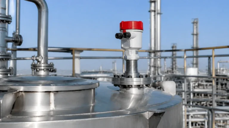
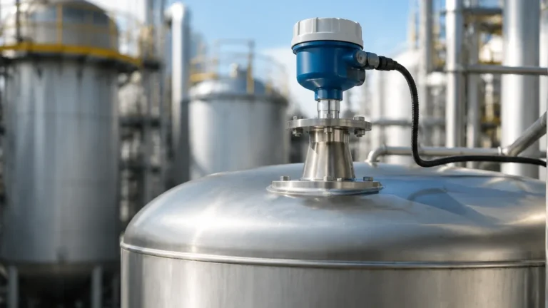
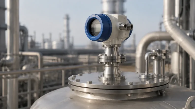
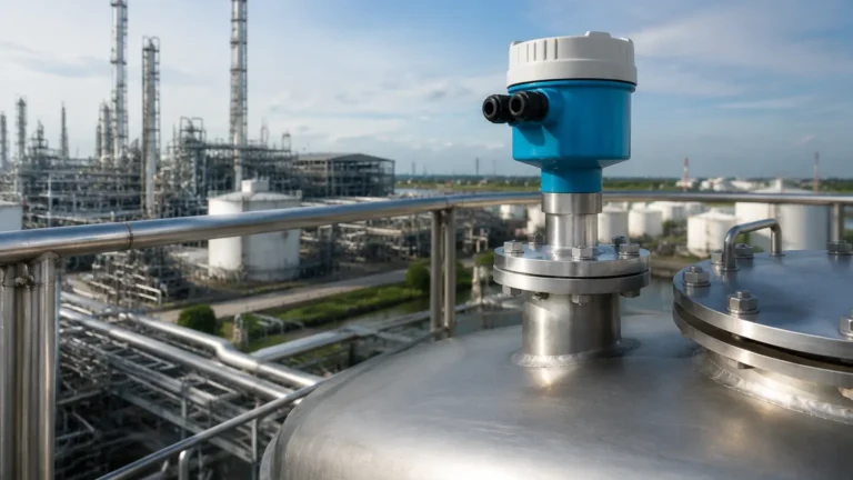
5408 Radar Level Transmitter PDF
5408 Radar Level Transmitter PDF
In the landscape of industrial process automation, the demand for precise, non-contacting level measurement has led to the widespread adoption of frequency-modulated continuous wave (FMCW) technology. For many instrumentation engineers and procurement specialists, the search for a 5408 radar level transmitter pdf is the first step in understanding how high-performance radar sensors can solve complex level monitoring challenges. This guide provides a comprehensive technical overview of radar measurement principles, selection criteria, and installation best practices essential for modern industrial applications.
1. Understanding Radar Measurement Principles
Before selecting a specific instrument, it is critical to understand the physics behind the measurement. Industrial Radar Level Meters primarily utilize two distinct methods: Pulse Radar and Frequency Modulated Continuous Wave (FMCW).
Pulse Radar
Pulse radar systems emit a short microwave pulse and measure the "Time of Flight" (ToF) for the signal to travel to the product surface and back. While effective for simple applications, pulse radar often struggles with low-dielectric materials or environments with significant vapor and turbulence.
FMCW Radar Technology
The technology typically described in a 5408 radar level transmitter pdf is FMCW. Unlike pulse radar, an FMCW transmitter sends a continuous signal with a constantly changing frequency (a frequency sweep). When the reflected signal is received, it is compared to the signal being emitted at that exact moment. The difference in frequency is directly proportional to the distance to the material surface.
Advantages of FMCW include:
* Higher Accuracy: FMCW provides a much higher resolution, often within ±1 mm (0.04 in).
* Superior Signal-to-Noise Ratio: It can filter out background noise more effectively, making it suitable for tanks with internal obstructions like agitators or heating coils.
* Better Performance on Low Dielectrics: By integrating the signal over a longer period, FMCW can detect weaker echoes from materials like oils or plastic pellets.
2. Technical Specifications and Selection Criteria
When reviewing a 5408 radar level transmitter pdf, engineers focus on several key performance metrics. These specifications determine whether the device is suitable for a specific process vessel or storage tank.
Key Performance Metrics
1. Frequency Range: Most high-end transmitters operate in the 24 GHz to 80 GHz range. Higher frequencies allow for smaller antennas and narrower beam angles, which are ideal for avoiding internal tank structures.
2. Measurement Range: Modern units can measure distances from 0.5 meters (1.6 ft) up to 40 meters (131 ft) or more, depending on the antenna type and dielectric constant of the media.
3. Safety Integrity Level (SIL): For hazardous chemical or oil and gas applications, SIL 2 or SIL 3 certification is often required to ensure the device meets international safety standards for overfill prevention.
Selection Table: Radar Technology Comparison
| Feature | 26 GHz Radar | 80 GHz Radar | Guided Wave Radar (GWR) |
| :— | :— | :— | :— |
| Measurement Type | Non-contact | Non-contact | Contacting (Probe) |
| Beam Angle | Moderate (8° – 20°) | Narrow (3° – 6°) | N/A (Follows probe) |
| Turbulence Resistance | Good | Excellent | Excellent |
| Dust/Vapor Sensitivity | Moderate | Low | Low |
| Internal Obstructions | Sensitive | Less Sensitive | Not Sensitive |
| Typical Application | Large storage tanks | Small process vessels | Low dielectric liquids |
3. Antenna Selection and Process Connections
The antenna is the interface between the electronic transmitter and the process environment. The choice of antenna affects the beam angle and the sensitivity of the Radar Level Meters.
* Cone Antennas: The most common type, suitable for a wide range of pressures and temperatures. They are robust and easy to clean.
* Process Seal Antennas: These feature a flat face (often PTFE) that protects the antenna from corrosive vapors or condensation. They are ideal for chemical storage.
* Parabolic Antennas: Used for very long distances or solid materials where the signal might be scattered. The large diameter provides a very narrow, high-gain beam.
4. Installation and Commissioning Considerations
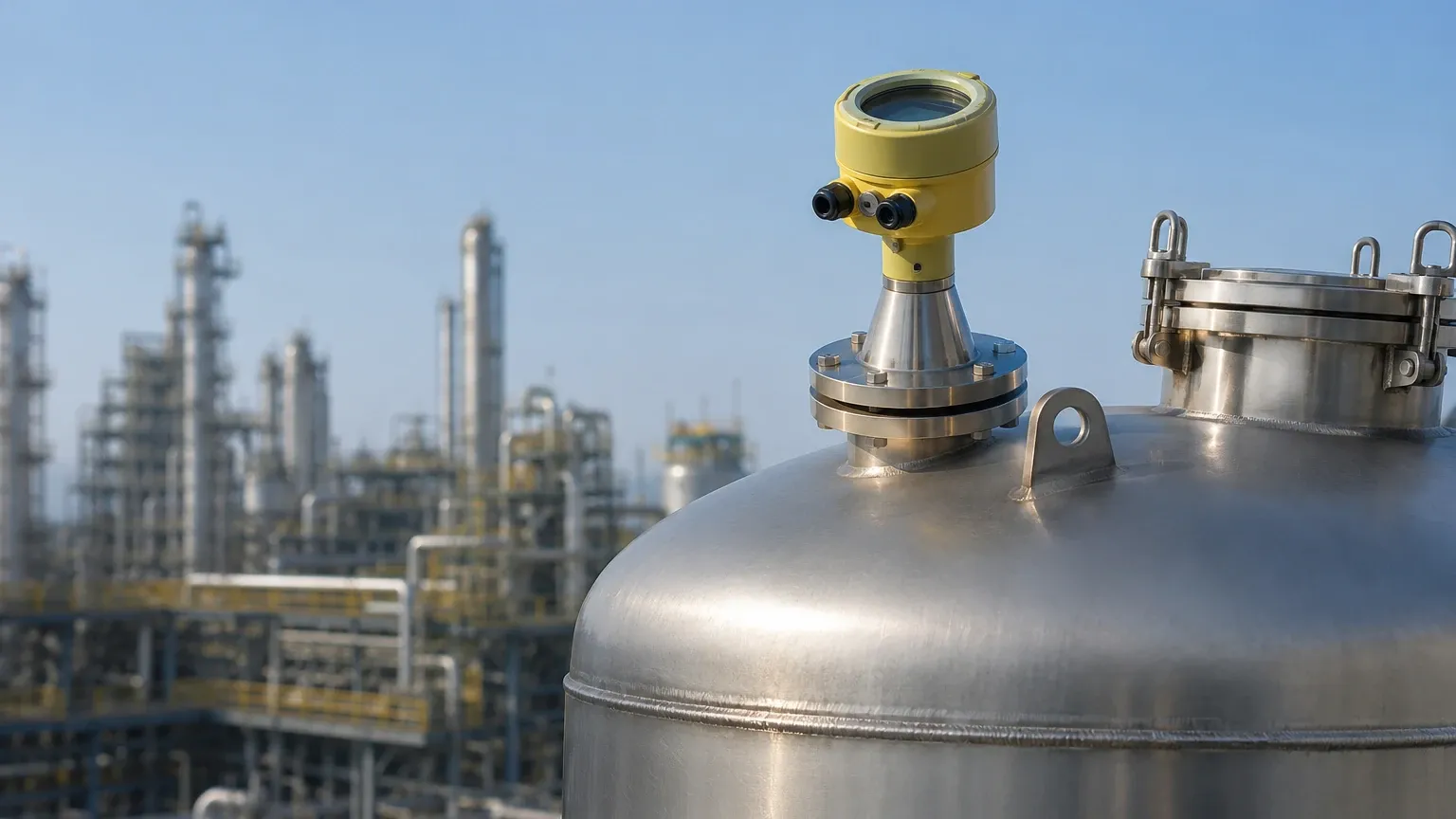
Proper installation is the single most important factor in ensuring the reliability of a radar level transmitter. Technical documentation, such as the 5408 radar level transmitter pdf, usually highlights specific "no-go" zones within a tank.
Nozzle Placement
* Distance from Wall: The transmitter should be mounted at a distance from the tank wall, typically 1/6th of the tank diameter, to avoid interference from wall reflections.
* Avoid the Center: Never mount a radar transmitter in the exact center of a domed-roof tank. The dome can act as a parabolic reflector, concentrating noise and false echoes directly back at the sensor.
* Nozzle Height: The nozzle should be as short as possible. If the nozzle is too long, the radar signal may reflect off the inside of the nozzle before entering the tank, creating a "dead zone" at the top of the measurement range.
Obstructions and Agitators
If the tank contains agitators, baffles, or ladders, the radar beam must be positioned to avoid these structures. If avoidance is impossible, modern transmitters allow for "False Echo Suppression." During commissioning, the engineer maps the empty tank; the software then ignores static reflections from internal structures, focusing only on the moving echo from the liquid surface.
5. Application Limitations and Environmental Factors
While radar is highly versatile, it is not a universal solution. Engineers must account for the following limitations:
1. Dielectric Constant ($ε_r$): Radar relies on the reflection of electromagnetic waves. Materials with a very low dielectric constant (like liquefied gases or some dry solids) reflect very little energy. If the $ε_r$ is below 1.4, special high-sensitivity settings or guided wave radar may be required.
2. Heavy Foam: Dense, thick foam can absorb the radar signal entirely, leading to a loss of echo. However, light, airy foam is usually transparent to the radar, allowing it to see the liquid level underneath.
3. Extreme Turbulence: Rapidly moving surfaces can scatter the radar signal. While FMCW algorithms can compensate for this, it may reduce the overall accuracy or response time.
4. Vacuum and Pressure: While radar works well in a vacuum (as electromagnetic waves do not require a medium), high-pressure environments can change the propagation speed of the signal slightly, requiring a correction factor in the transmitter settings.
6. Maintenance and Troubleshooting
One of the primary benefits of non-contacting Radar Level Meters is the minimal maintenance required. Since no parts touch the process media, there is no mechanical wear.
Common Troubleshooting Steps:
* Check for Build-up: If the process involves sticky or crystallizing media, check the antenna face for build-up. Many transmitters include a "Signal Quality Metrics" feature that alerts operators when the antenna needs cleaning.
* Verify Power Supply: Radar transmitters, especially 4-20mA loop-powered units, require a stable voltage (typically 12-42V DC). Voltage drops can cause intermittent signal loss.
* Signal Loss (LOE): If the device reports a "Loss of Echo," check if the surface has dropped below the dielectric threshold or if a new obstruction has entered the beam path.
7. Frequently Asked Questions (FAQ)
Q: Can I use a radar level transmitter for solids?
A: Yes, but it requires careful selection. Solids have an angle of repose that can deflect the signal away from the transmitter. High-frequency (80 GHz) units with specialized solids algorithms are recommended.
Q: What is the difference between 2-wire and 4-wire transmitters?
A: 2-wire (loop-powered) transmitters use the same pair of wires for power and the 4-20mA signal, simplifying wiring. 4-wire transmitters have separate power connections, allowing for higher power consumption, which can be useful for driving more powerful signals or heating elements in extremely cold environments.
Q: How does the 5408 series handle condensation?
A: High-quality transmitters use circular polarization and specialized lens designs to minimize the impact of water droplets on the antenna. In many cases, the FMCW signal can "see through" moderate condensation without loss of accuracy.
Q: Is a 5408 radar level transmitter pdf sufficient for DIY installation?
A: While the PDF provides the technical boundaries, installation should be performed by a qualified instrumentation technician. Configuration often requires specialized software (like PACTware or AMS Device Manager) or a HART handheld communicator.
Conclusion
Selecting the right level measurement technology is a balance of process requirements, safety standards, and budget. The 5408 series represents a pinnacle of reliability for demanding industrial environments. By understanding the FMCW principle, adhering to strict installation guidelines, and accounting for the dielectric properties of the media, engineers can ensure long-term, maintenance-free operation. For more detailed technical specifications and to explore various antenna and housing configurations, professionals are encouraged to Review product options and application support to find the ideal solution for their specific industrial needs.