Vega Guided Wave Radar Level Transmitter Manual
Engineering Guide to Guided Wave Radar Level Transmitters: Principles, Installation, and Selection
In the landscape of industrial automation, accurate level measurement is a cornerstone of process safety and efficiency. Among the various technologies available, Guided Wave Radar (GWR) has emerged as a robust solution for challenging environments where traditional non-contact methods might fail. This guide explores the technical foundations of GWR technology, drawing on engineering best practices often detailed in documentation such as a vega guided wave radar level transmitter manual, and provides a framework for selecting the right instrumentation for complex industrial applications.
Understanding the Measurement Principle: Time Domain Reflectometry (TDR)
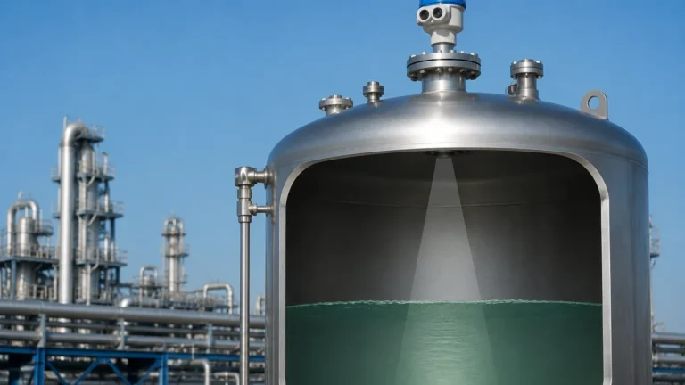
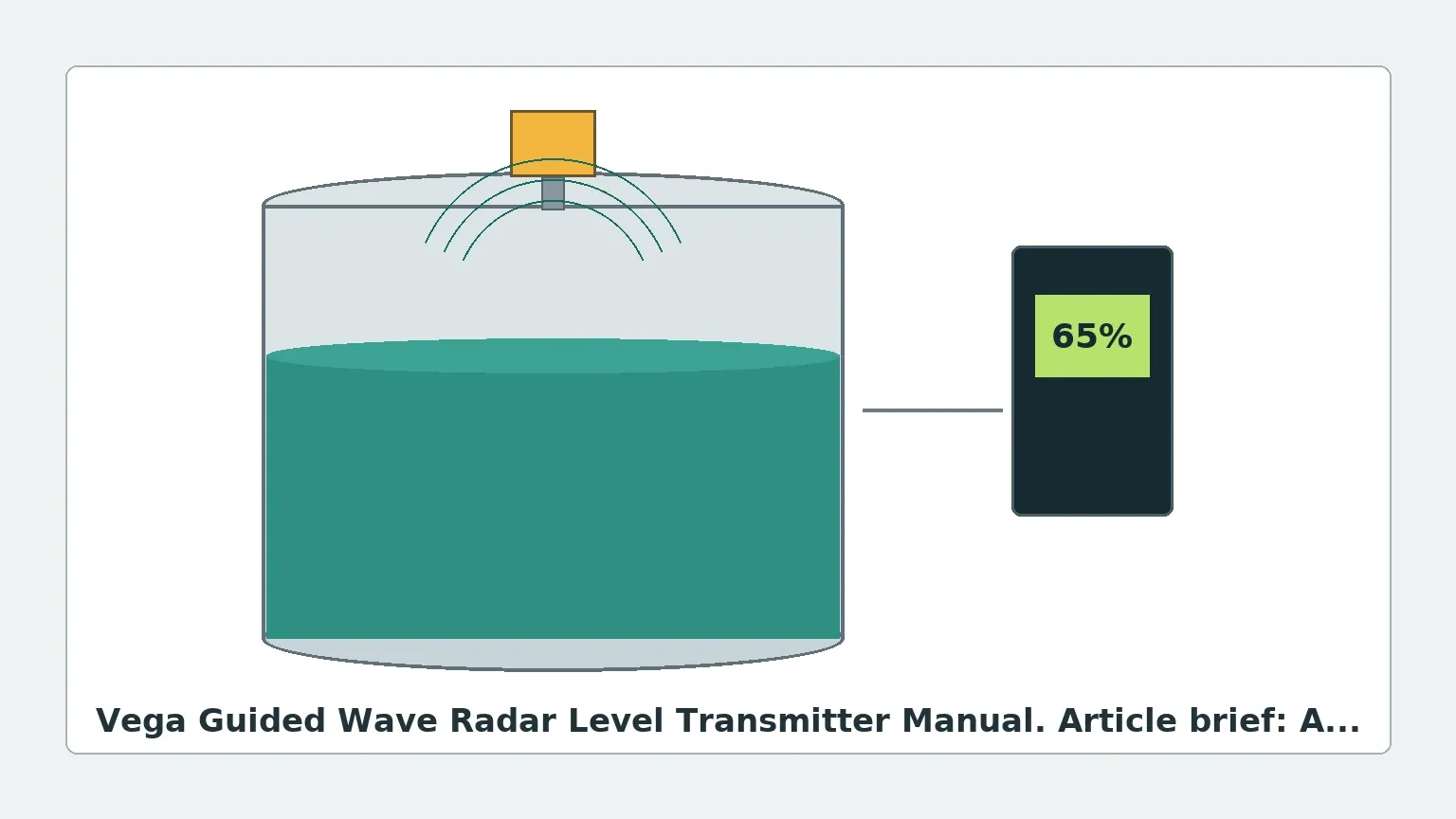
Guided Wave Radar operates on the principle of Time Domain Reflectometry (TDR). Unlike non-contact Radar Level Meters that emit electromagnetic pulses through the air, GWR systems conduct low-power microwave pulses along a physical waveguide—typically a metal rod, cable, or coaxial probe.
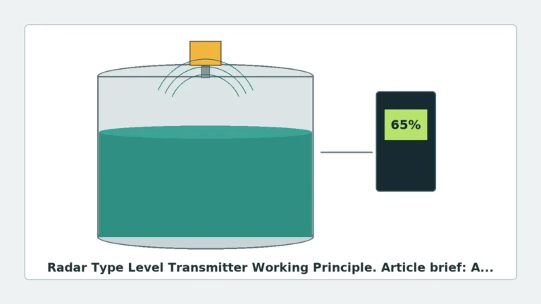
When these pulses reach the surface of the medium being measured (liquid or solid), a portion of the microwave energy is reflected back to the transmitter. This reflection occurs because of a change in the dielectric constant (εr) between the upper medium (usually air or gas) and the process medium. The transmitter electronics measure the time-of-flight—the interval between the emission of the pulse and the reception of the echo. Since the speed of light is constant, the distance to the product surface is calculated using the formula:
Distance = (Speed of Light × Time-of-Flight) / 2
Once the distance is known, the transmitter subtracts this value from the total tank height (the zero point) to determine the level. Because the signal is physically guided, it is less susceptible to attenuation caused by foam, steam, dust, or turbulent surfaces, making it a preferred choice for high-pressure and high-temperature vessels.
Key Components and Configuration
When consulting a vega guided wave radar level transmitter manual or similar technical documentation, engineers will find that the system's performance is heavily dependent on the probe configuration. There are three primary types of waveguides used in industrial GWR:
1. Single Rod/Cable Probes: These are the most common and versatile. They are suitable for a wide range of liquids and are easier to clean. However, they are more sensitive to electromagnetic interference and require a certain distance from tank walls and internal obstructions.
2. Twin Rod/Cable Probes: These consist of two parallel conductors. They provide a more concentrated signal than single probes and are often used for liquids with lower dielectric constants in larger tanks.
3. Coaxial Probes: These feature a rod inside a metal tube. The signal is completely contained within the tube, making it immune to tank internals, foam, or mounting nozzle interference. This is the ideal choice for low-dielectric fluids like hydrocarbons (εr < 2.0).
Selection Criteria for Industrial Applications
Selecting the appropriate GWR instrument requires a deep understanding of the process media and the vessel geometry. The following table provides a general selection framework based on typical industrial requirements.
Table 1: GWR Selection Matrix
| Feature | Rod Probe | Cable Probe | Coaxial Probe |
| :— | :— | :— | :— |
| Max Range | Up to 6m (20ft) | Up to 75m (246ft) | Up to 6m (20ft) |
| Media State | Liquids / Slurries | Solids / Powders / Liquids | Clean Liquids |
| Dielectric Constant (εr) | > 1.6 | > 1.6 | > 1.4 |
| Viscosity | Medium to High | Low to Medium | Very Low (Clean only) |
| Turbulence Resistance | High | High | Excellent |
| Internal Obstructions | Sensitive | Sensitive | Immune |
The Role of the Dielectric Constant
The dielectric constant is the most critical factor in GWR performance. A higher εr results in a stronger reflection. For media with a very low dielectric constant, such as liquefied gases or certain oils, the signal may pass through the surface, requiring the use of "End of Probe" (EoP) tracking or coaxial probes to ensure measurement stability.
Installation Considerations and Best Practices
Proper installation is vital to ensure the accuracy and longevity of the level meter. While specific steps are outlined in a vega guided wave radar level transmitter manual, several universal engineering constraints apply to all GWR installations:
1. Nozzle Geometry
The mounting nozzle should be as short and wide as possible. For single-rod probes, the nozzle diameter should ideally be at least 50mm (2 inches). If the nozzle is long and narrow, it can create "ringing" or parasitic reflections that interfere with the near-zone measurement (the upper 300mm to 500mm of the tank).
2. Clearance from Tank Walls
Single and twin probes must maintain a minimum distance from the tank wall and internal structures like ladders, agitators, or heating coils. A general rule of thumb is to maintain a clearance of at least 300mm (12 inches) to prevent the signal from jumping to the wall instead of the fluid surface.
3. Probe Anchoring
In tanks with high agitation or flow, cable probes must be anchored to the bottom of the vessel to prevent swaying. However, the anchor must allow for thermal expansion of the cable to avoid mechanical stress on the transmitter head.
4. Bypass Pipes and Stillwells
For applications involving heavy foam or extremely turbulent surfaces, installing the GWR probe inside a bypass pipe or a stillwell is recommended. This creates a calm surface for measurement and acts similarly to a coaxial probe, concentrating the signal energy.
Calibration and Commissioning
Commissioning a GWR transmitter involves more than just powering the unit. Modern industrial instruments require a "False Signal Suppression" or "Mapping" process. During this phase, the transmitter scans the empty tank to identify and record reflections from stationary internals (like nozzles or welds). The electronics then ignore these static echoes, focusing only on the dynamic echo from the product surface.
Key parameters to define during setup include:
* Tank Height: The distance from the sensor reference point to the bottom of the tank (4mA or 0% level).
* Blocking Distance (Upper Dead Band): The zone near the top of the probe where measurement is not possible or accurate.
* Dielectric Constant Setting: Configuring the expected εr of the medium to optimize signal processing thresholds.
Limitations and Application Risks
While GWR is highly versatile, it is not a universal solution. Engineers must be aware of the following limitations:
* Build-up and Coating: While GWR can handle some coating, significant build-up of conductive or viscous material on the probe can attenuate the signal or cause "bridging," leading to false high-level readings.
* Mechanical Stress: In tall silos containing heavy solids (like grain or cement), the pull-down forces on a cable probe can reach several tons. The vessel roof and the probe assembly must be rated for these structural loads.
* Minimum Dielectric Limits: If the εr is below 1.4, the reflection may be too weak for standard GWR. In such cases, specialized high-sensitivity electronics or bypass chambers are required.
Comparison: GWR vs. Non-Contact Radar
Engineers often debate between Guided Wave Radar and non-contact Radar Level Meters. The choice usually depends on the environment:
* GWR is superior in high-pressure steam applications (like boiler drum level) because the waveguide ensures the signal reaches the surface despite changes in the vapor space's dielectric properties.
* Non-contact Radar is preferred for highly corrosive media where no wetted parts should touch the liquid, or in applications where a probe would interfere with a heavy-duty agitator.
Frequently Asked Questions (FAQ)
Q: Can a GWR probe be shortened in the field?
A: Yes, most rod and cable probes can be cut to length during installation. However, the new length must be updated in the transmitter software to maintain accuracy. Coaxial probes are generally more difficult to modify and should be ordered to the correct length.
Q: Does the tank material affect GWR measurement?
A: For coaxial probes, the tank material is irrelevant. For single-rod probes, a metal tank top or a metal mounting flange is required to act as a ground plane for the microwave pulse. On plastic tanks, a special mounting plate or a dual-probe system is necessary.
Q: How does GWR handle interface measurement?
A: GWR is exceptionally good at measuring the interface between two liquids (e.g., oil over water). The pulse reflects off the upper surface (oil) and continues through the low-dielectric liquid to reflect off the higher-dielectric lower liquid (water). Both levels can often be reported simultaneously.
Conclusion
Guided Wave Radar represents a pinnacle of reliability in industrial level instrumentation. By understanding the core principles of TDR and adhering to the installation guidelines found in a vega guided wave radar level transmitter manual or Welk's technical documentation, process engineers can solve the most difficult level measurement challenges. Whether dealing with the turbulent surfaces of a chemical reactor or the dusty environment of a cement silo, the guided nature of GWR provides a level of certainty that few other technologies can match. For optimal results, always verify the dielectric properties of your media and ensure the probe geometry aligns with your vessel's mechanical constraints.
Download Vega Guided Wave Radar Level Transmitter Manual as a PDF