Sewer Lift Stations
Sewer Lift Stations
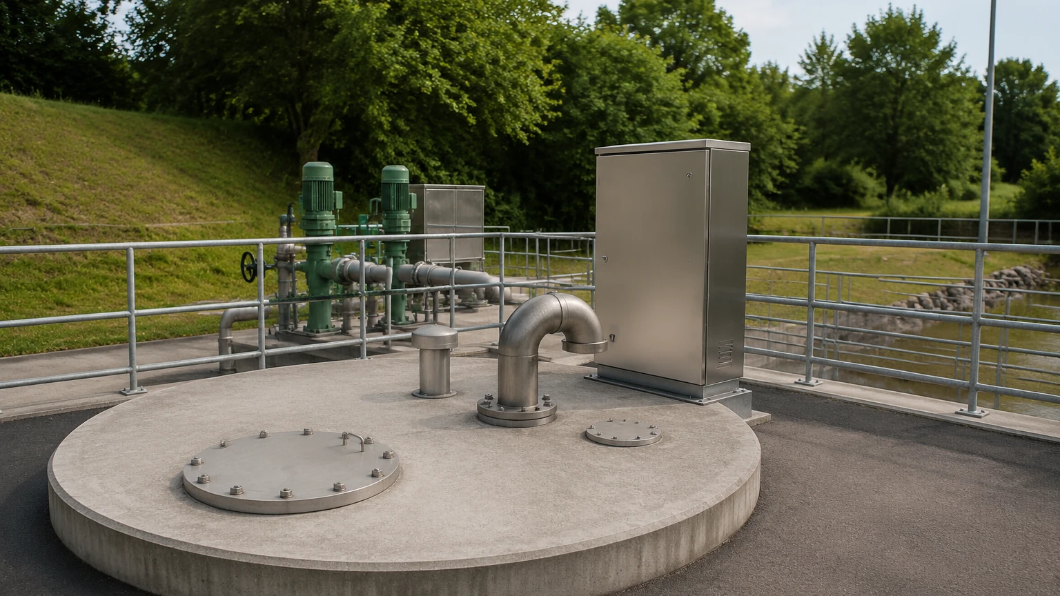
In modern municipal and industrial wastewater management, sewer lift stations serve as critical infrastructure components. These systems are designed to move wastewater from lower to higher elevations when the natural topography does not allow for gravity-driven flow. Because these stations often operate in remote or underground locations, the reliability of their automated systems—specifically level measurement—is paramount to preventing overflows, environmental contamination, and costly pump failures.
For engineers and facility managers, selecting the correct instrumentation for sewer lift stations requires a deep understanding of the fluid dynamics, the chemical composition of the effluent, and the physical constraints of the wet well. This guide explores the technical principles of level measurement within these environments and provides a framework for selecting the most robust solutions.
The Role of Level Measurement in Lift Station Automation
Sewer lift stations function by collecting wastewater in a reservoir known as a wet well. As the level of the liquid rises, sensors trigger the pumps to activate and move the fluid to a higher-elevation gravity sewer or directly to a treatment plant.
A typical control logic for sewer lift stations involves several setpoints:
1. Low-Level Cutout: Ensures pumps shut off before they run dry, preventing cavitation and motor damage.
2. Lead Pump Start: The level at which the primary pump begins operation.
3. Lag Pump Start: A higher level that triggers a secondary pump if the inflow exceeds the capacity of a single pump.
4. High-Level Alarm: A critical threshold indicating a potential overflow or pump failure, usually triggering a telemetry alert.
Accurate measurement is essential because the environment inside a wet well is notoriously harsh. Sensors must contend with hydrogen sulfide (H2S) gas, heavy turbulence, thick layers of grease (FOG—fats, oils, and grease), and floating debris.
Core Level Measurement Principles
Before selecting a device, it is important to understand the physical principles governing the most common measurement technologies used in sewer lift stations.
1. Ultrasonic Level Measurement (Non-Contact)
Ultrasonic sensors operate on the "time-of-flight" principle. The sensor emits a high-frequency sound pulse that travels through the air, reflects off the liquid surface, and returns to the transducer. The distance is calculated based on the speed of sound.
* Advantages: No moving parts and no contact with the corrosive wastewater.
* Limitations: Ultrasonic waves can be absorbed by heavy foam or deflected by steam and heavy turbulence. Temperature fluctuations also affect the speed of sound, requiring integrated temperature compensation.
2. Radar Level Measurement (Non-Contact)
Radar sensors, particularly those operating at 80GHz, use Frequency Modulated Continuous Wave (FMCW) technology. They emit microwave signals that reflect off the liquid surface. Unlike ultrasonic waves, microwaves are unaffected by air temperature, vacuum, or pressure changes.
* Advantages: Highly resistant to steam, condensation, and foam. The narrow beam angle of 80GHz radar allows for installation in narrow wet wells with internal obstructions like ladders or pipes.
* Limitations: Generally higher initial investment compared to ultrasonic or hydrostatic sensors.
1
3. Hydrostatic Pressure Measurement (Contact)
Hydrostatic transmitters are submerged at the bottom of the wet well. They measure the pressure exerted by the liquid column above them. Since pressure is directly proportional to the height of the liquid (based on its specific gravity), the sensor provides a continuous level reading.
* Advantages: Unaffected by foam or surface turbulence. Simple to install by suspending the sensor via a reinforced cable.
* Limitations: The sensor is in constant contact with the media. In sewer lift stations, grease and solids can build up on the sensing diaphragm, requiring regular cleaning to prevent drift.
4. Float Switches (Point Level)
Float switches are mechanical devices that tip when the liquid reaches a certain height, opening or closing an electrical circuit. In modern sewer lift stations, they are rarely used for primary control but are indispensable as redundant back-ups for high-level alarms.
Selection Criteria for Wet Well Environments
Choosing the right technology depends on the specific characteristics of the lift station. Engineers should evaluate the following factors:
* Presence of Foam and Grease: If the station frequently handles detergents or high-fat content, foam will likely be present. In these cases, radar is superior to ultrasonic sensors. If using hydrostatic sensors, a "clog-free" flush diaphragm design is necessary.
* Well Geometry: Narrow wells with multiple pump pipes and access ladders require sensors with a narrow beam angle (such as 80GHz radar) to avoid false echoes from internal structures.
* Chemical Compatibility: The presence of H2S gas is common in sewer lift stations. Sensors and cables must be constructed from corrosion-resistant materials like PVDF, 316L stainless steel, or high-grade PUR/PE cables.
* Maintenance Accessibility: If the wet well is deep or requires confined space entry for maintenance, non-contact sensors (Radar/Ultrasonic) are preferred because they can be serviced from the top of the well without removing the unit from the effluent.
Technology Comparison Table
| Feature | Ultrasonic | Radar (80GHz) | Hydrostatic | Float Switches |
| :— | :— | :— | :— | :— |
| Measurement Type | Continuous (Non-contact) | Continuous (Non-contact) | Continuous (Contact) | Point Level (Contact) |
| Accuracy | ±0.25% of range | ±2 mm (0.08 in) | ±0.1% to 0.5% | N/A |
| Foam Resistance | Poor to Moderate | Excellent | Excellent | Good |
| Grease Build-up | No Impact | No Impact | High Impact | Moderate Impact |
| Maintenance | Low | Very Low | Moderate | Moderate |
| Typical Range | 0.3m – 15m | 0.1m – 30m+ | 0m – 20m | Fixed |
Installation Best Practices for Sewer Lift Stations
Proper installation is as critical as sensor selection. Even the most advanced radar sensor will fail if positioned incorrectly.
1. Avoid the Inlet Stream: Never install a level sensor directly above or near the inflow pipe. The falling water creates extreme turbulence and air entrainment, which can lead to erratic readings.
2. Dead Zone (Blanking Distance): Every non-contact sensor has a "dead zone" near the transducer face where it cannot measure. Ensure the sensor is mounted high enough so that the maximum liquid level never enters this zone.
3. Stilling Wells: In cases of extreme turbulence, a stilling well (a vertical pipe submerged in the liquid) can be used to provide a calm surface for the sensor to measure. This is particularly useful for hydrostatic and ultrasonic sensors.
4. Cable Management: For hydrostatic sensors, use a proper cable suspension clamp to prevent the cable from stretching or being damaged by the weight of the sensor. Ensure the vent tube in the cable is protected from moisture to allow for atmospheric pressure compensation.
5. Mounting Position: Sensors should be mounted perpendicular to the liquid surface. For radar, ensure the signal beam has a clear path to the lowest point of the well to ensure accurate measurement even when the well is nearly empty.
Common Risks and Limitations
While modern instrumentation is highly reliable, sewer lift stations present unique risks that can compromise system integrity:
* H2S Corrosion: Hydrogen sulfide gas can permeate lower-quality cable jackets and corrode internal wiring. Always specify cables designed for wastewater environments.
* Signal Interference: In metal wet wells, "multi-path" reflections can occur. Modern radar sensors use software algorithms to mask these static echoes, but proper positioning remains the first line of defense.
* Power Surges: Lift stations are often located at the end of electrical lines and are susceptible to lightning strikes and power surges. Using sensors with integrated surge protection or installing external lightning arrestors is highly recommended.
* FOG Accumulation: In many municipal sewer lift stations, fats, oils, and grease (FOG) form a thick crust on the surface. This crust can become hard enough to support the weight of a float switch, preventing it from tipping. Non-contact sensors are generally immune to this, though they may measure the top of the grease layer rather than the liquid wastewater.
Maintenance and Reliability Protocols
To ensure the longevity of the level measurement system, a proactive maintenance schedule should be implemented:
* Visual Inspection: Every 3 to 6 months, inspect the sensor for signs of corrosion or physical damage. For hydrostatic sensors, check the diaphragm for grease buildup.
* Calibration Verification: Periodically compare the sensor's output against a manual tape measure reading. Most modern digital sensors do not "drift" in the traditional sense, but environmental changes (like heavy grease buildup on the walls) can affect signal quality.
* Redundancy: In critical lift stations, it is common practice to use two different technologies—for example, a radar sensor for continuous control and a mechanical float switch for a high-level backup. This diversity protects against common-mode failures.
Frequently Asked Questions (FAQs)
Q: Can I use an ultrasonic sensor if there is heavy steam in the wet well?
A: Steam changes the density of the air, which affects the speed of sound. While some ultrasonic sensors have temperature compensation, heavy steam can still cause significant errors. Radar is a much more reliable choice for steaming environments.
Q: How do I handle a wet well that is very narrow?
A: Use a high-frequency (80GHz) radar sensor. These units have a very narrow beam angle (often as low as 3 degrees), allowing them to measure the liquid level without hitting the walls or internal pipes.
Q: Is it necessary to use explosion-proof sensors in sewer lift stations?
A: Many sewer lift stations are classified as Class I, Division 1 or 2 (or ATEX Zone 0/1) environments due to the potential for methane and other explosive gases. You must check local regulations and the site's hazardous area classification before selecting a sensor.
Q: How deep can hydrostatic sensors measure?
A: Hydrostatic sensors can be designed for very deep applications, often up to 100 meters (328 feet) or more. However, for standard sewer lift stations, they are typically calibrated for ranges between 2 and 10 meters (6.5 to 33 feet).
Conclusion
Effective management of sewer lift stations depends on selecting level measurement technology that matches the specific challenges of the site. Whether utilizing the precision of 80GHz radar or the simplicity of hydrostatic pressure, understanding the measurement principles and installation requirements is key to operational success. For engineers looking to optimize their wastewater infrastructure, reviewing advanced sensor options is the first step toward reducing maintenance costs and preventing environmental incidents.
For more detailed technical specifications and to explore our full range of industrial measurement instruments, please visit our Main Page. Our team provides professional-grade radar, ultrasonic, and hydrostatic solutions tailored for the demanding conditions of global wastewater applications.