Temperature E
Temperature E
In industrial process control, the accuracy of level measurement is often compromised by environmental and process variables. Among these, temperature is perhaps the most significant. Often referred to in engineering circles as "temperature e"—shorthand for temperature effects or temperature errors—this variable influences the physical properties of the media being measured as well as the mechanical and electronic performance of the measurement instrumentation itself. Understanding how temperature interacts with different measurement principles is essential for selecting the correct technology for a specific application.
Whether dealing with cryogenic liquids at -196°C or molten salts exceeding 500°C, engineers must account for thermal expansion, density shifts, and the speed of signal propagation. This guide examines the relationship between temperature and level measurement, providing a technical framework for evaluating and mitigating temperature-related inaccuracies.
Measurement Principles and Thermal Sensitivity
Before selecting a level meter, it is necessary to understand how specific measurement technologies respond to temperature fluctuations. Each principle—be it acoustic, electromagnetic, or pressure-based—has a unique relationship with the thermal environment.
Ultrasonic Level Measurement
Ultrasonic sensors operate by emitting a sound pulse and measuring the time it takes for the echo to return from the surface of the medium. The fundamental equation is $D = (v \times t) / 2$, where $v$ is the speed of sound. However, the speed of sound in air (or any gas) is highly dependent on temperature. In air, the speed of sound changes by approximately 0.17% for every degree Celsius change. Without active compensation, a 20°C shift in ambient temperature can result in a measurement error of over 3%. Most modern ultrasonic transmitters include an integrated thermistor to compensate for this effect, but they may struggle if there is a significant temperature gradient between the sensor face and the liquid surface.
Radar (FMCW and Pulse) Level Measurement
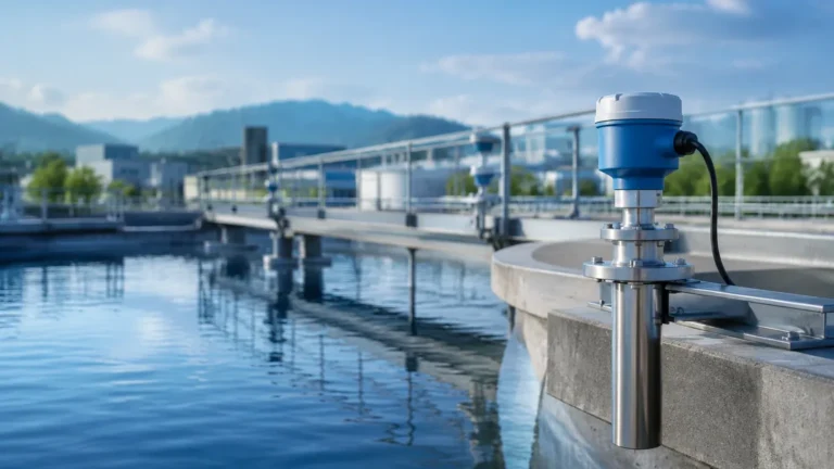
Radar level meters use electromagnetic waves, which travel at the speed of light. Unlike sound, the speed of light is not significantly affected by air temperature, pressure, or vapor composition. This makes radar one of the most stable technologies for high-temperature applications. However, temperature still plays a role in the "temperature e" context regarding the dielectric constant ($ε_r$) of the medium. For some fluids, the dielectric constant decreases as temperature increases, which can weaken the reflected signal. Furthermore, extreme heat can damage the sensitive electronics in the sensor head if proper cooling or standoff mounting is not utilized.
Hydrostatic Pressure Measurement
Hydrostatic level transmitters calculate level based on the formula $P = ρgh$, where $ρ$ is the density of the liquid. Density is an inverse function of temperature; as a liquid heats up, it expands and its density decreases. If a transmitter is calibrated for a specific density at 20°C but the process runs at 80°C, the level reading will be erroneously high because the sensor cannot distinguish between a change in height and a change in density. For high-precision applications, a secondary temperature input is required to perform real-time density compensation.
Magnetic Level Gauges
Magnetic level gauges rely on a float containing a magnet assembly that moves with the liquid level. Temperature affects these systems in two ways: thermal expansion of the float chamber and changes in the buoyancy of the float due to liquid density shifts. If the liquid density drops below the float's design limit due to extreme heat, the float may sink, leading to a total loss of measurement.
Analyzing Temperature E: Key Evaluation Criteria
When evaluating the "temperature e" impact on a project, engineers should focus on three primary areas: the sensor's operating limits, the medium's physical transformation, and the installation environment.
1. Operating Temperature Limits
Every instrument has two distinct temperature ratings: the process temperature (the temperature of the media) and the ambient temperature (the temperature of the air surrounding the transmitter housing). For high-temperature steam applications, for instance, a standard radar sensor might require a cooling extension or a specialized antenna material like PTFE or PEEK to withstand the heat. Users should consult the Main Page of technical data sheets to verify that both the wetted parts and the electronics housing are rated for the intended environment.
2. Density and Phase Changes
In the chemical and oil and gas industries, temperature fluctuations can cause liquids to approach their boiling points or undergo phase changes. For hydrostatic and displacement-based sensors, the error introduced by density changes can be calculated using the coefficient of thermal expansion. If the coefficient is known, the "temperature e" can be mitigated through PLC-based calculations or smart transmitters with built-in compensation tables.
3. Signal Attenuation and Vapor Clouds
High temperatures often lead to increased evaporation, creating a dense vapor layer above the liquid. In ultrasonic measurement, this vapor can change the medium through which the sound travels, leading to significant signal attenuation or false readings. Radar is generally immune to these vapors, but at very high temperatures and pressures (such as in boiler drums), the dielectric constant of the steam itself can become high enough to require a propagation delay correction.
Selection Table for Temperature-Specific Applications
The following table provides a general guideline for selecting level measurement technologies based on process temperature ranges.
| Technology | Temperature Range (Typical) | Sensitivity to Temperature E | Recommended Use Case |
| :— | :— | :— | :— |
| Ultrasonic | -40°C to 95°C | High (Speed of sound changes) | Water treatment, open channels |
| Radar (80GHz) | -40°C to 200°C+ | Low (Electronics limit only) | Chemical reactors, storage tanks |
| Hydrostatic | -40°C to 120°C | Medium (Density changes) | Vented tanks, deep wells |
| Guided Wave Radar | -196°C to 450°C | Very Low | High-pressure steam, cryogenics |
| Magnetic Gauge | -196°C to 400°C | Medium (Float buoyancy) | Visual indication, high-pressure bypass |
Installation Considerations for Thermal Management
Proper installation is the most effective way to minimize temperature-induced errors and extend the lifespan of the instrument. Even the most robust sensor can fail if thermal conduction and radiation are not managed.
* Standoff Pipes and Nozzles: For high-temperature tanks, mounting the sensor on a standoff pipe allows the process heat to dissipate before reaching the transmitter electronics. This is particularly common with radar and ultrasonic sensors.
* Heat Sinks and Cooling Jackets: In extreme environments, such as furnaces or molten metal processing, water-cooled or air-cooled jackets can be wrapped around the sensor housing to maintain the electronics within their safe operating range (usually below 80°C).
* Remote Seals: For hydrostatic pressure transmitters, a remote seal with a capillary tube can be used. This allows the pressure-sensing diaphragm to be in contact with the hot process fluid while the actual transmitter is mounted several meters away at ambient temperature.
* Insulation: While it may seem counterintuitive, insulating the mounting nozzle can sometimes prevent "cold spots" where vapors might condense on the sensor face, causing signal blockage. However, the transmitter housing itself should never be insulated, as it needs to dissipate its own internal heat.

Limitations and Common Risks
Despite advances in compensation algorithms, certain temperature-related risks remain inherent to level measurement:
1. Thermal Shock: Rapid changes in temperature (e.g., during a Clean-in-Place or CIP process in food production) can cause mechanical stress on ceramic diaphragms or glass seals, leading to premature failure.
2. Condensation and Icing: In cryogenic applications, ice buildup on the sensor can block signals entirely. In high-heat applications, condensation on the antenna can cause a "near-blanking" effect where the sensor only sees the moisture on its own lens.
3. Electronic Drift: All electronic components have a temperature coefficient. Even if the measurement principle is stable, the internal circuitry may experience "drift" if exposed to temperatures beyond its calibrated range.
Frequently Asked Questions (FAQ)
Q: How do I calculate the error in my hydrostatic level reading if the temperature rises?
A: The error is proportional to the change in density. If your liquid density at 20°C is 1000 kg/m³ and it drops to 980 kg/m³ at 60°C, your level reading will be approximately 2% higher than the actual physical level. You can correct this by multiplying the reading by the ratio of (Actual Density / Calibration Density).
Q: Can ultrasonic sensors be used in outdoor tanks subject to direct sunlight?
A: Yes, but with caution. Direct sunlight can heat the sensor housing significantly higher than the actual air temperature, leading the internal compensation thermistor to provide an incorrect reading. A sunshade is highly recommended for outdoor ultrasonic installations.
Q: Is radar always the best choice for high-temperature applications?
A: Generally, yes. Radar is the most resistant to the "temperature e" factors that plague other technologies. However, for extremely high pressures combined with high temperatures, Guided Wave Radar (GWR) is often preferred because it can be equipped with specialized vapor compensation probes.
Q: What is the impact of temperature on the dielectric constant?
A: For most liquids, the dielectric constant decreases as temperature increases. This means the reflection at the liquid surface becomes weaker. If you are measuring a low-dielectric fluid like a hydrocarbon, you must ensure the radar has enough sensitivity to detect the surface at the maximum process temperature.
Conclusion
Managing "temperature e" in level measurement requires a holistic approach that considers the physics of the media, the limitations of the sensor, and the mechanics of the installation. By understanding the measurement principles and implementing proper compensation and protection strategies, engineers can ensure accurate and reliable data even in the most thermally challenging environments. For a comprehensive review of instrument specifications and application-specific support, engineers should evaluate the technical resources available on the Main Page to match the right technology with their specific thermal requirements.