Flow Gp
Flow Gp
In the landscape of industrial process control, the integration of level and flow measurement is critical for operational efficiency, safety, and regulatory compliance. The term "flow gp," often associated with general-purpose flow monitoring and level-to-flow conversion, represents a fundamental requirement across water treatment, chemical processing, and industrial automation. Accurate measurement in these environments requires a deep understanding of the physical principles governing fluid dynamics and the electronic sensing technologies used to capture data.
For engineers and facility managers, selecting the right instrumentation involves balancing precision requirements with environmental constraints. Whether managing a wastewater effluent stream or monitoring chemical storage tanks, the choice of technology—ranging from radar and ultrasonic to hydrostatic sensors—determines the reliability of the entire control loop. For a comprehensive overview of available industrial instrumentation, professionals can refer to the Main Page of the Welk product catalog.
Core Measurement Principles for Industrial Applications
Before selecting a flow gp solution, it is essential to understand the underlying measurement principles. In many general-purpose applications, flow is not measured directly by a mechanical meter but is instead derived from level measurements in standardized structures like flumes or weirs, or calculated via pressure differentials.
Radar Level Measurement (Non-Contact)
Radar level meters utilize Time of Flight (ToF) technology. The sensor emits a high-frequency electromagnetic wave (typically in the 26GHz or 80GHz range) toward the medium's surface. The wave reflects off the surface and returns to the receiver. The distance is calculated based on the time interval and the constant speed of light.
Modern 80GHz radar sensors offer a narrow beam angle, which is particularly beneficial in flow gp applications where space is limited or where internal tank obstructions might cause signal interference. Because radar waves do not require a medium for propagation, they are unaffected by vacuum, pressure, or temperature fluctuations in the vapor space.
Ultrasonic Level Measurement (Non-Contact)
Ultrasonic sensors also use the ToF principle but rely on sound waves rather than electromagnetic pulses. A piezoelectric crystal in the transducer converts electrical energy into mechanical sound pulses. These pulses bounce off the liquid surface and return to the sensor.
In flow gp contexts, ultrasonic sensors are frequently used in open-channel flow measurement. However, because the speed of sound is affected by air temperature, these sensors must include integrated temperature compensation to maintain accuracy. They are cost-effective but can be sensitive to heavy foam, dust, or high-pressure steam.
Hydrostatic Level Measurement (Contact)
Hydrostatic transmitters measure the pressure exerted by a liquid column at a specific depth. Based on the formula $P = \rho gh$ (where $P$ is pressure, $\rho$ is density, $g$ is gravity, and $h$ is height), the sensor determines the liquid level. In flow gp scenarios involving vented tanks or open reservoirs, hydrostatic sensors provide a robust, submersible solution that is immune to surface turbulence or foam.
Technology Selection Criteria for Flow GP Applications
Choosing the appropriate technology requires an evaluation of the media, the environment, and the required accuracy. The following table provides a comparison of the primary technologies used in general-purpose flow and level monitoring.
| Feature | Radar (80GHz) | Ultrasonic | Hydrostatic | Magnetic Gauge |
| :— | :— | :— | :— | :— |
| Accuracy | ±2 mm (0.08 in) | ±0.25% of range | ±0.1% to ±0.5% | ±5 mm to ±10 mm |
| Measuring Range | Up to 120m (393 ft) | Up to 15m (49 ft) | Up to 200m (656 ft) | Up to 6m (20 ft) |
| Media Type | Liquids and Solids | Primarily Liquids | Liquids Only | Liquids Only |
| Process Temp. | -40 to +250°C | -40 to +80°C | -20 to +80°C | -40 to +400°C |
| Effect of Foam | Minimal | Significant | None | None |
| Installation | Top-mounted | Top-mounted | Submerged/Side | Side-mounted |
Media Characteristics
In flow gp applications, the dielectric constant ($ε_r$) of the liquid is a critical factor for radar. Liquids with low dielectric constants (like oils) reflect less energy than those with high constants (like water). For ultrasonic sensors, the presence of heavy foam can absorb the sound pulse, leading to signal loss. Hydrostatic sensors are density-dependent; if the liquid density changes significantly due to temperature shifts or chemical composition, the level reading must be compensated.
Environmental Factors
If the application involves high-pressure vessels (exceeding 3 bar / 43.5 psi), non-contact ultrasonic sensors are generally unsuitable due to the attenuation of sound waves in pressurized gases. Radar and hydrostatic sensors are better suited for these conditions. For outdoor flow gp installations, such as irrigation channels, the sensor housing must have an appropriate Ingress Protection (IP) rating, typically IP67 or IP68, to withstand weather exposure.
Engineering Installation and Configuration
Proper installation is the most significant factor in ensuring the longevity and accuracy of a flow gp system. Even the most advanced sensor will fail if the installation geometry is incorrect.
Mounting Position and Nozzles
For radar and ultrasonic sensors, the device should be mounted away from the tank wall to avoid "ringing" or side-lobe reflections. A common rule of thumb is to mount the sensor at least 200 mm (8 inches) from the wall for every 1 meter (3.3 feet) of tank height. If the sensor is mounted on a nozzle, the nozzle diameter and height must be sized to ensure the signal beam does not clip the nozzle edge, which creates a "dead zone" or false reflection.
Dead Zones (Blocking Distance)
Every non-contact sensor has a minimum distance, known as the "dead zone" or "blocking distance," where it cannot measure accurately. For ultrasonic sensors, this is typically 0.25m to 0.5m (10 to 20 inches). If the liquid level rises into this zone, the sensor may report a full tank or an error. Engineers must ensure the sensor is mounted high enough to accommodate the maximum expected flow or level without entering the dead zone.
Stilling Wells and Bypass Chambers
In applications with heavy turbulence, such as near a pump intake or an agitator, a stilling well (a vertical pipe with vent holes) can be used to provide a calm surface for the sensor to measure. This is particularly common in flow gp setups where the surface of the liquid is constantly moving. For magnetic level gauges, a bypass chamber is mounted to the side of the tank, allowing for clear visual indication and electronic transmission without interfering with the main process volume.

Overcoming Common Challenges in Flow GP Systems
Industrial environments present several challenges that can compromise flow gp data integrity. Addressing these during the design phase prevents costly downtime.
1. Vapor and Condensation: In chemical tanks, condensation can form on the sensor face. While many radar sensors use PTFE-faced antennas to shed droplets, ultrasonic sensors may fail if a water film covers the transducer. Using a parabolic or horn antenna for radar helps focus the beam and minimize the impact of buildup.
2. Surface Turbulence: Rapid filling or emptying of a vessel creates waves. High-speed signal processing and software algorithms, such as "False Echo Suppression," allow modern sensors to ignore these transient disturbances and track the true average level.
3. Signal Integration: Most flow gp instruments provide a 4-20mA output with HART protocol, Modbus RS485, or Foundation Fieldbus. Ensuring the sensor's communication protocol matches the facility's PLC (Programmable Logic Controller) or SCADA system is vital for seamless data integration.
Limitations and Troubleshooting
While modern instrumentation is highly reliable, there are inherent limitations to each technology.
* Radar: The primary limitation is the dielectric constant. If the medium has a $ε_r < 1.4$, a guided wave radar (GWR) using a probe may be necessary instead of a non-contact model.
* Ultrasonic: These sensors cannot operate in a vacuum because sound waves require a medium (air/gas) to travel. They are also sensitive to changes in the gas composition (e.g., high concentrations of CO2 or methane) which alter the speed of sound.
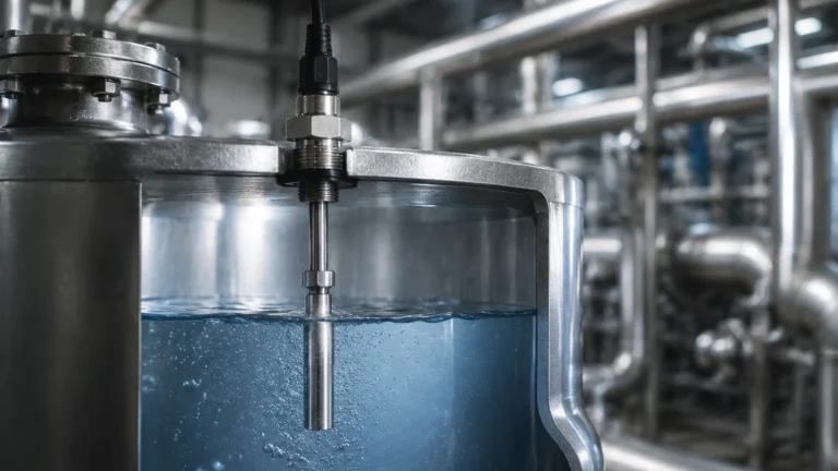
* Hydrostatic: These are contact-based sensors. If the liquid is corrosive or contains abrasive solids, the diaphragm can be damaged. Selecting the correct diaphragm material, such as Hastelloy or Ceramic, is essential for longevity.
To explore specific product options and receive application-specific engineering support, users are encouraged to visit the Main Page for detailed technical documentation.
Frequently Asked Questions (FAQ)
Q: How does a flow gp system calculate volume from level?
A: Most advanced level transmitters include a built-in "strapping table" or linearization function. By inputting the dimensions of the tank or the geometry of the weir/flume, the sensor automatically converts the measured level (meters/mm) into volume (liters/m³) or flow rate (m³/h).
Q: Can radar be used for flow gp in open channels?
A: Yes. Radar is increasingly preferred over ultrasonic for open-channel flow because it is unaffected by wind, ambient temperature changes, or solar heating of the air above the water.
Q: What maintenance is required for these sensors?
A: Non-contact sensors like radar and ultrasonic are virtually maintenance-free as they have no moving parts. However, periodic inspection is recommended to ensure no significant buildup of material is occurring on the sensor face. Hydrostatic sensors should be checked for sediment buildup around the diaphragm in wastewater applications.
Q: What is the difference between 2-wire and 4-wire systems?
A: A 2-wire system uses the same pair of wires for both power and the 4-20mA signal, making it easier to install. A 4-wire system uses separate wires for power (often 220V AC or 24V DC) and signal, which is usually required for high-power devices like certain long-range ultrasonic or radar units with heated displays.
By adhering to these engineering principles and selection guidelines, industrial operators can implement flow gp solutions that provide accurate, real-time data, ensuring the stability and safety of their process environments.