Ultrasonic Water Level Sensor
Ultrasonic Water Level Sensor
In the landscape of industrial automation and process control, the ultrasonic water level sensor has established itself as a cornerstone technology for non-contact measurement. These instruments are widely utilized across water treatment facilities, chemical processing plants, and irrigation systems due to their reliability, ease of maintenance, and cost-effectiveness. As a professional manufacturer, Welk provides these solutions to meet the rigorous demands of global industrial applications, ensuring accurate data collection for both liquid storage and open-channel flow monitoring.
Selecting the appropriate level measurement technology requires a deep understanding of the underlying physics and the specific environmental variables of the application site. This guide provides a comprehensive technical overview of ultrasonic sensors, their selection criteria, and the practical considerations necessary for successful deployment in B2B environments.
Understanding the Measurement Principle
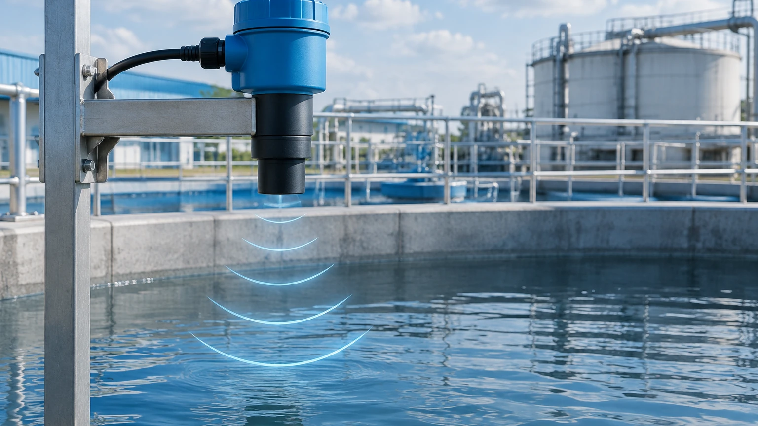
The operation of an ultrasonic water level sensor is based on the "Time-of-Flight" (ToF) principle. The instrument's transducer contains a piezoelectric crystal that converts electrical energy into mechanical vibrations, emitting high-frequency sound pulses—typically between 20 kHz and 200 kHz—toward the surface of the water.
Once the sound wave hits the water surface, it is reflected back to the sensor. The transducer then acts as a receiver, converting the returning mechanical pulse back into an electrical signal. The sensor’s internal microprocessor calculates the distance between the sensor face and the water surface using the following formula:
Distance (D) = (Speed of Sound (c) × Time (t)) / 2
Where:
* c is the speed of sound in air (approximately 343 meters per second at 20°C).
* t is the total time elapsed from emission to reception.
The division by two accounts for the fact that the sound pulse traveled to the surface and back. To determine the actual level of the water, the calculated distance (D) is subtracted from the total tank height or the sensor's installation height (Empty Distance).
The Role of Temperature Compensation
Because the speed of sound is highly dependent on the temperature of the medium through which it travels (air), industrial-grade ultrasonic water level sensors include integrated temperature sensors. For every degree Celsius change, the speed of sound changes by approximately 0.6 m/s. Without automatic temperature compensation, a 10°C shift could result in a measurement error of nearly 1.8%. High-quality sensors adjust the calculation in real-time to maintain accuracy across varying seasonal or process temperatures.
Key Evaluation Criteria for Industrial Selection
When specifying an ultrasonic water level sensor for a project, engineers must evaluate several technical parameters to ensure the device performs within the required tolerances of the application.
1. Measuring Range and Dead Zone
Every ultrasonic sensor has a maximum range (often up to 15 or 30 meters) and a minimum distance known as the "Dead Zone" or "Blocking Distance." The dead zone is the area immediately in front of the transducer where the sensor cannot accurately process a return signal because the transducer is still vibrating from the emission. Typically, this ranges from 0.25m to 0.8m depending on the frequency. It is critical to install the sensor high enough so that the maximum water level never enters this dead zone.
2. Beam Angle and Signal Spread
The ultrasonic pulse does not travel in a straight line; it spreads out in a cone shape. The beam angle (usually between 5° and 12°) determines the footprint of the signal at a given distance. If the beam is too wide, it may hit tank walls, ladders, or agitators, resulting in "false echoes." Selecting a sensor with a narrower beam angle is often necessary for tall, narrow tanks.
3. Output Signals and Integration
For integration into SCADA or PLC systems, sensors must provide standard industrial outputs. Common options include:
* 4-20mA Analog: The standard for long-distance signal transmission with high noise immunity.
* RS485/Modbus RTU: Digital communication allowing for multiple sensors on a single bus and remote configuration.
* Relay Outputs: Integrated switches for high/low-level alarms or pump control.
4. Material Compatibility
While the sensor is non-contact, the transducer face is exposed to the atmosphere within the tank. For clean water, ABS or PVC housings are sufficient. However, in wastewater or chemical applications involving corrosive vapors, PVDF (Polyvinylidene Fluoride) or PTFE (Teflon) faces are required to prevent degradation.
Practical Selection Guide and Comparison
The following table outlines typical configurations for common industrial water level applications to assist in the initial procurement phase.
| Application Type | Typical Range | Recommended Housing | Key Feature Required |
| :— | :— | :— | :— |
| Small Chemical Tank | 0.5m – 5m | PVDF / Corrosive Resistant | Narrow Beam Angle |
| Wastewater Wet Well | 1m – 10m | IP68 Rated / Submersible | Submergence Shield |
| Open Channel Flow | 0.2m – 3m | Weatherproof / UV Resistant | Built-in Flume/Weir Formulas |
| Deep Reservoir | 2m – 20m | High Power Transducer | Advanced Signal Processing |
| Irrigation Ditch | 0.5m – 5m | Low Power / Solar Ready | Modbus RTU Output |
For a broader view of available technologies including radar and hydrostatic options, engineers should consult the Main Page for detailed product specifications.
Installation Best Practices and Considerations
Correct installation is the most significant factor in the long-term performance of an ultrasonic water level sensor. Even the most advanced sensor will fail to provide accurate data if positioned incorrectly.
Positioning and Orientation
* Perpendicularity: The transducer face must be perfectly parallel to the water surface. Even a few degrees of tilt can cause the reflected signal to bounce away from the receiver, leading to signal loss.
* Location: Avoid mounting the sensor in the center of a circular tank, as this can concentrate parasitic reflections. Similarly, do not mount it too close to the wall (maintain a distance of at least 200mm for most models).
* Inflow Avoidance: Never install the sensor directly above the point where water enters the tank. Turbulence and air entrainment at the inflow point will scatter the ultrasonic signal.
Managing Obstructions
Internal tank structures like pipes, ladders, or bracing can interfere with the ultrasonic beam. Modern sensors utilize "False Echo Suppression" software, which allows the user to map out static obstructions. The sensor records the echoes from these fixed objects and ignores them in future calculations, focusing only on the moving echo from the water surface.
Environmental Protection
For outdoor installations, a sunshade or protective canopy is recommended. While the sensor is temperature-compensated, direct solar radiation can heat the sensor housing significantly above the ambient air temperature, leading to localized errors in the compensation algorithm.
Limitations and Environmental Risks
While highly versatile, the ultrasonic water level sensor is not a universal solution. Certain process conditions can attenuate or distort the sound waves, leading to unreliable readings.
1. Heavy Foam: Surface foam acts as an acoustic absorber. If the foam is thick and dense, it may absorb the ultrasonic pulse entirely, resulting in a "Lost Echo" error. In these cases, radar or hydrostatic transmitters are preferred.
2. Vapor and Steam: High concentrations of steam or chemical vapors change the density of the air. Since the speed of sound depends on medium density, this can lead to significant measurement drift. If the process involves boiling water or heavy evaporation, non-contact radar is a more stable choice.
3. Vacuum or High Pressure: Ultrasonic waves require a medium (air/gas) to travel. They cannot function in a vacuum. Furthermore, high-pressure environments significantly alter the speed of sound and the efficiency of the piezoelectric transducer.
4. Turbulence and Waves: While minor ripples are manageable, heavy turbulence can scatter the signal. This can often be mitigated by using a "stilling well" (a vertical pipe that dampens surface movement) or by increasing the damping/averaging time in the sensor's software settings.
Frequently Asked Questions (FAQs)
Q: Can an ultrasonic water level sensor measure through a closed plastic tank lid?
A: No. Ultrasonic waves are reflected by solid boundaries. The sensor must have a clear line of sight to the liquid or be installed via a threaded or flanged opening in the tank top.
Q: What is the difference between an integrated and a remote ultrasonic sensor?
A: An integrated (compact) sensor has the transducer and electronics in one housing. A remote system separates the transducer from the control unit (transmitter), which is useful if the measurement point is difficult to access or if the display needs to be mounted at eye level far from the tank.
Q: How often does an ultrasonic sensor need calibration?
A: In stable environments, these sensors are "set and forget." However, for regulatory compliance in water treatment, an annual verification against a manual tape measure is standard practice. No physical wear occurs because the device is non-contact.
Q: Can wind affect the accuracy of the sensor?
A: In outdoor applications, strong winds can potentially deflect the ultrasonic pulse or create air density fluctuations. For large-scale reservoir monitoring, mounting the sensor inside a protective shroud or stilling well helps maintain signal integrity.
Conclusion
The ultrasonic water level sensor remains a primary choice for industrial water management due to its lack of moving parts and its ability to provide accurate readings without contacting the process media. By carefully considering the dead zone, beam angle, and environmental factors like foam and vapor, engineers can implement a robust measurement solution that reduces maintenance overhead and improves process efficiency.
For technical support, customized OEM services, or to explore our full range of industrial measurement instruments, please visit our Main Page to connect with our application engineering team.