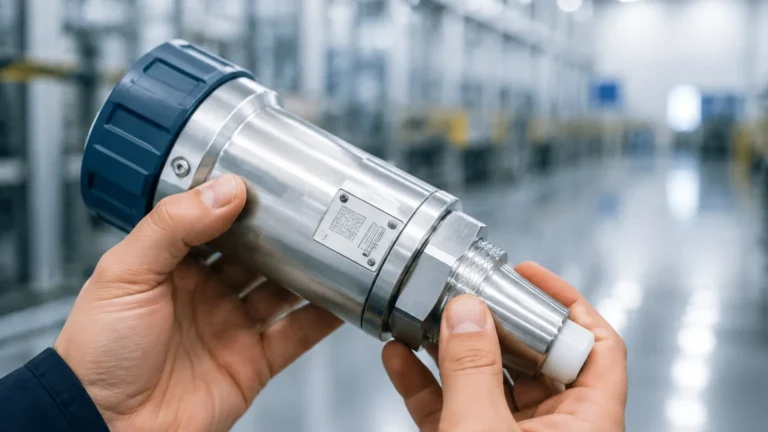
Anderson Differential Pressure Indicator
Anderson Differential Pressure Indicator
In the landscape of industrial process control, the Anderson differential pressure indicator stands as a specialized instrument designed primarily for the rigorous demands of the food, beverage, dairy, and pharmaceutical industries. These sectors require measurement solutions that not only provide high accuracy but also adhere to strict sanitary standards. Differential pressure (DP) measurement is a versatile technique used to determine liquid level, flow rates across orifices, and the performance of filtration systems. Understanding the mechanical and electronic nuances of these indicators is essential for engineers tasked with maintaining process integrity and safety.
Understanding the Principle of Differential Pressure Measurement
Differential pressure measurement is based on the calculation of the difference between two pressure points in a system. In level measurement applications, specifically within closed or pressurized vessels, a single pressure sensor at the bottom of the tank cannot distinguish between the pressure exerted by the liquid head and the pressure of the gas blanket above the liquid.
To solve this, a differential pressure indicator utilizes two sensing elements. The "high-pressure" side is typically connected to the bottom of the vessel, while the "low-pressure" side is connected to the top (the headspace). The device subtracts the headspace pressure from the total bottom pressure, leaving only the hydrostatic pressure exerted by the liquid column. The relationship is defined by the formula:
P = ρ · g · h
Where:
* P is the hydrostatic pressure.
* ρ (Rho) is the density of the fluid.
* g is the acceleration due to gravity (approximately 9.81 m/s²).
* h is the height of the liquid.
By knowing the density of the medium, the indicator can provide a precise readout of the liquid level. This principle is also applied to filter monitoring, where the indicator measures the pressure drop across a filter element. A significant increase in differential pressure suggests that the filter is becoming clogged and requires maintenance or replacement.
Key Features of the Anderson Differential Pressure Indicator
The Anderson-style indicator is distinguished by its sanitary design, which is engineered to eliminate "dead legs" or areas where bacteria could proliferate. These instruments are often constructed to meet 3-A Sanitary Standards and EHEDG guidelines.
Material Construction
Most units feature 316L stainless steel wetted parts, polished to a high degree of smoothness (often measured in Ra, or roughness average). This ensures that the device can withstand Clean-in-Place (CIP) and Steam-in-Place (SIP) cycles without degrading or contaminating the product.
Diaphragm Seals
Unlike standard industrial DP transmitters that might use impulse lines, sanitary indicators often utilize flush-mount diaphragm seals. These seals use a food-grade fill fluid (such as glycerin or mineral oil) to transmit pressure from the process diaphragm to the internal sensing element. This design prevents the process fluid from entering the instrument internals.
Display and Output
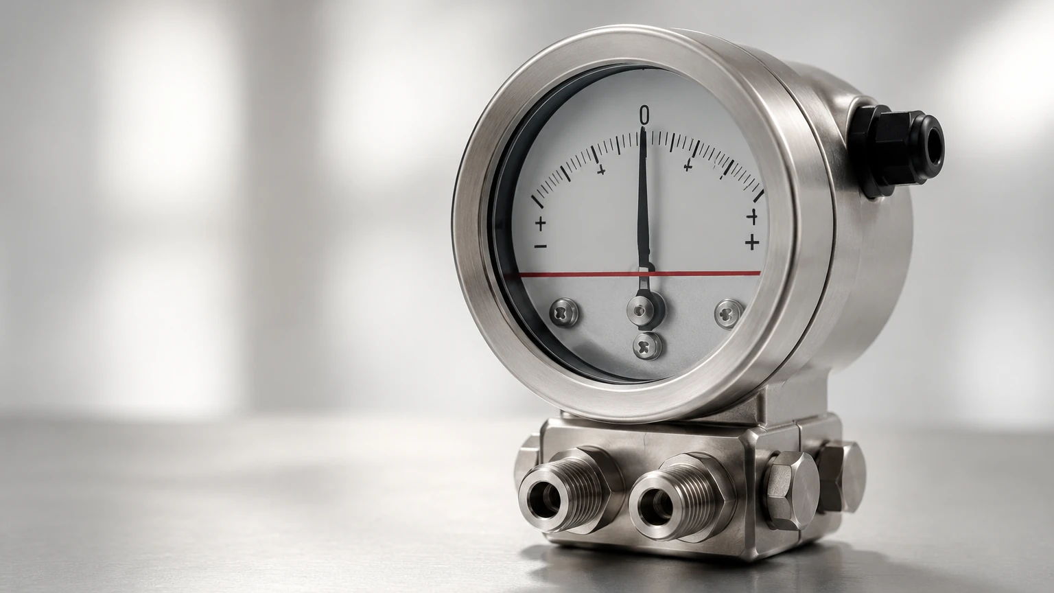
Modern indicators provide local digital displays for immediate operator feedback, alongside standard industrial outputs like 4-20mA or HART protocols for integration into a PLC or SCADA system. Mechanical versions, often used for local-only monitoring, utilize a bellows or diaphragm-actuated pointer.
Applications in Sanitary and Industrial Processes
The utility of an Anderson differential pressure indicator extends across various critical process points. While primarily known for sanitary applications, the engineering principles apply broadly to any environment requiring high-reliability pressure monitoring.
1. Pressurized Storage Tanks: In the dairy industry, milk is often stored in large, pressurized silos. DP indicators provide accurate level data regardless of the vapor pressure inside the tank.
2. Filtration Systems: In beverage production, monitoring the pressure drop across membrane filters or carbon beds is vital to ensure product clarity and prevent pump cavitation.
3. Heat Exchangers: By monitoring the differential pressure between the product side and the media side of a plate heat exchanger, operators can detect fouling or internal leaks.
4. Separator Control: In oil and gas or chemical processing, DP indicators help manage the interface levels between two immiscible liquids of different densities.
For those evaluating broader level measurement technologies, such as radar or ultrasonic sensors, visiting the Main Page provides a comprehensive overview of alternative instruments that may complement DP indicators in complex automation environments.
Selection Criteria for DP Indicators and Transmitters
Choosing the correct differential pressure indicator requires a detailed analysis of the process conditions. Engineers should use the following table as a baseline for evaluating whether a DP indicator is the appropriate choice compared to other common technologies.
| Feature | Differential Pressure Indicator | Radar Level Meter | Ultrasonic Sensor |
| :— | :— | :— | :— |
| Measurement Type | Contact (via Diaphragm) | Non-contact | Non-contact |
| Accuracy | High (±0.1% to ±0.5% FS) | Very High (±1mm to ±3mm) | Moderate (±0.25% of range) |
| Sanitary Rating | Excellent (Flush Diaphragm) | Excellent | Good |
| Pressure Limit | High (Up to 400 bar / 5800 psi) | Moderate | Low (Usually < 3 bar) |
| Density Sensitivity | High (Requires constant density) | None | None |
| Foam Resistance | Excellent | Good (Frequency dependent) | Poor |
Key Evaluation Questions:
* What is the maximum process temperature? Sanitary DP indicators must be rated for SIP temperatures, often reaching 140°C (284°F).
* Is the fluid density constant? Since DP measurement relies on density to calculate level, significant fluctuations in density will lead to measurement errors unless compensated for in the control system.
* What are the mounting requirements? Ensure the tank has the appropriate tri-clamp or flanged fittings to accommodate the dual sensing points.
Installation Best Practices for Accurate Level Measurement
The accuracy of an Anderson differential pressure indicator is heavily dependent on proper installation. Improperly mounted sensors can introduce "zero shifts" or respond slowly to process changes.
Mounting Positions
The high-pressure sensor must be located at the lowest point of the desired measurement range. The low-pressure sensor (for pressurized tanks) should be located in the vapor space, well above the maximum liquid level to prevent liquid from entering the reference line.
Capillary Tubes and Thermal Effects
In many sanitary setups, the indicator is connected to the seals via capillary tubes. These tubes must be protected from extreme temperature fluctuations. If one capillary is in the sun and the other is in the shade, the expansion of the fill fluid can create a false pressure differential. It is recommended to lag or insulate capillary lines together to ensure they experience the same ambient conditions.
Zeroing the Instrument
After installation but before the tank is filled, the instrument must be zeroed. This accounts for the mounting position and the weight of the fill fluid in the capillaries. For atmospheric tanks, the low-pressure port is simply vented to the atmosphere, often through a moisture-excluding breather.
Limitations and Troubleshooting
While highly reliable, DP indicators have specific limitations that operators must be aware of to ensure long-term performance.
* Density Changes: As noted, if the process fluid's temperature changes significantly, its density changes. Without a temperature-compensated PLC algorithm, the indicated level will drift even if the actual volume remains constant.
* Diaphragm Damage: The thin stainless steel diaphragms are sensitive. Mechanical cleaning with brushes or high-pressure water jets can dent the diaphragm, leading to permanent calibration shifts.
* Gas Entrapment: In systems using impulse lines rather than flush seals, gas bubbles trapped in a liquid-filled line (or liquid trapped in a gas-filled line) will cause significant errors. This is why "wet leg" or "dry leg" configurations must be meticulously maintained.
Common Troubleshooting Steps:
1. Check for Leaks: Even a microscopic leak in the low-pressure side of a pressurized tank system will cause the indicated level to read higher than the actual level.
2. Verify Power Supply: For electronic transmitters, ensure the loop voltage is within the specified range (typically 12-36V DC).
3. Inspect for Build-up: In sticky applications like chocolate or heavy syrups, product can harden on the diaphragm, "masking" the pressure and causing sluggish response.
Frequently Asked Questions (FAQs)
Q: Can an Anderson differential pressure indicator be used for flow measurement?
A: Yes. When paired with a primary flow element like an orifice plate or Venturi tube, the DP indicator measures the pressure drop across the restriction, which is proportional to the square of the flow rate.
Q: How often should these instruments be calibrated?
A: In critical food and pharma applications, annual calibration is standard. However, if the process involves frequent SIP cycles or high-vibration environments, semi-annual checks are recommended.
Q: What is the difference between a "wet leg" and a "dry leg"?
A: A "dry leg" is used when the gas in the headspace will not condense at ambient temperatures. A "wet leg" is a reference line pre-filled with a compatible liquid, used when the headspace gas is likely to condense, which would otherwise create an unpredictable liquid column in the reference line.
Q: Is it possible to use a DP indicator on an open tank?
A: Yes, but it is often unnecessary. For an open (atmospheric) tank, a simple hydrostatic pressure transmitter at the bottom is sufficient, as the "low side" is the atmosphere itself. A DP indicator would only be used if there was a specific need to compare the tank pressure to another process point.
By adhering to these engineering guidelines and selection criteria, process managers can ensure that their Anderson differential pressure indicator provides the reliable data necessary for efficient and safe industrial operations. For further technical specifications on various level measurement technologies, including radar and ultrasonic systems, professionals are encouraged to Review product options and application support to find the optimal fit for their specific environmental challenges.