Water Level Sensors
Water Level Sensors
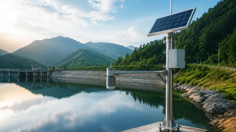
In industrial process control and environmental monitoring, the accurate measurement of liquid levels is a fundamental requirement. Water level sensors are specialized instruments designed to detect the position of a water surface relative to a fixed reference point. These sensors are critical in diverse sectors, ranging from municipal water treatment and wastewater management to complex chemical processing, oil and gas operations, and general industrial automation.
Selecting the appropriate technology requires a deep understanding of the physical principles governing the measurement, the environmental conditions of the application, and the specific requirements of the process. This guide provides a technical overview of the primary water level measurement technologies, their engineering principles, and practical selection criteria for B2B applications.
Understanding the Fundamentals of Water Level Measurement
Water level measurement can be categorized into two primary types: point level detection and continuous level measurement. Point level sensors (switches) indicate whether water has reached a specific height, often used for overfill protection or pump control. Continuous level sensors provide a real-time, analog or digital output representing the exact level throughout the entire range of a tank or vessel.
Before selecting an instrument, engineers must evaluate the "Main Page" of the application requirements, which includes the physical state of the water (clean, turbid, or corrosive), the presence of foam or turbulence, and the physical constraints of the installation site. For comprehensive technical data and product specifications, engineers often refer to the Main Page to review product options and application support.
Core Technologies and Measurement Principles
Modern industrial water level sensors utilize several distinct physical principles. Understanding these principles is the first step in ensuring long-term reliability and accuracy.
Hydrostatic Level Transmitters
Hydrostatic measurement is based on the principle that the pressure at a specific point in a static liquid is proportional to the height of the liquid column above it. The relationship is defined by the formula:
P = ρ × g × h
Where:
* P is the hydrostatic pressure (Pascal).
* ρ (rho) is the density of the water (kg/m³).
* g is the gravitational constant (approx. 9.81 m/s²).
* h is the height of the water column (meters).
Hydrostatic sensors typically use a stainless steel or ceramic diaphragm. As the water level rises, the pressure on the diaphragm increases, which is then converted into an electrical signal (usually 4-20mA). These sensors are available as submersible probes or externally mounted pressure transmitters. They are highly reliable for deep wells, reservoirs, and vented tanks where the water density remains relatively constant.
Ultrasonic Level Sensors
Ultrasonic sensors are non-contact devices that utilize Sound Navigation and Ranging (SONAR) principles. The sensor emits a high-frequency ultrasonic pulse (typically 20 kHz to 80 kHz) toward the water surface. The pulse reflects off the surface and returns to the sensor. By measuring the time-of-flight (ToF), the distance to the water surface is calculated:
Distance = (Speed of Sound × Time) / 2
Because the speed of sound in air is affected by temperature, industrial ultrasonic sensors like those from Welk include integrated temperature compensation. These sensors are ideal for open channels and tanks containing clean or slightly dirty water, provided there is no heavy foam or high-pressure vapor present.
Radar Level Meters
Radar level measurement uses high-frequency electromagnetic waves (microwaves), typically in the 26 GHz or 80 GHz range. Similar to ultrasonic sensors, radar sensors measure the time-of-flight. However, microwaves travel at the speed of light and are not significantly affected by air temperature, pressure, or vacuum conditions.
Radar technology is divided into two types:
1. Non-contact Radar: The sensor is mounted at the top of the tank and emits waves through the air. It is highly resistant to dust, vapor, and temperature fluctuations.
2. Guided Wave Radar (GWR): The microwave pulse travels along a physical probe (rod or cable). This technology is excellent for applications with low dielectric constants or where the surface is extremely turbulent.
Magnetic Level Gauges
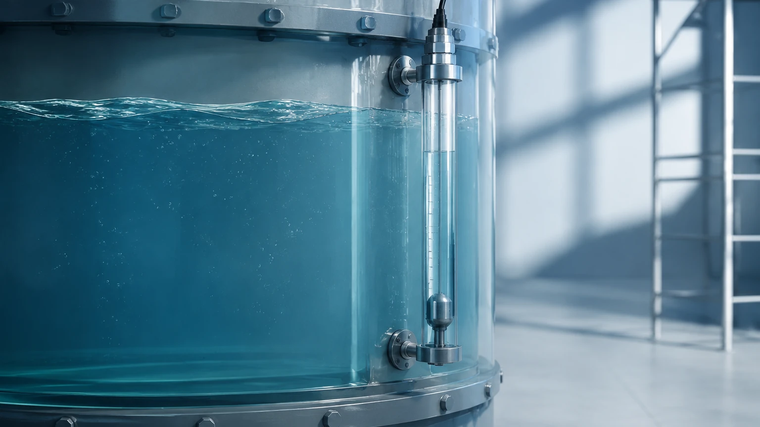
Magnetic level gauges are based on the principle of buoyancy and magnetic coupling. A float containing a permanent magnet moves up and down a bypass chamber connected to the vessel. As the float moves, it flips magnetic flaps or actuates a magnetic reed chain in a transmitter. This provides both a local visual indication and a remote electrical signal. These are preferred for high-pressure or high-temperature water applications where electronic components must be isolated from the process media.
Engineering Selection Criteria for Water Level Sensors
When specifying water level sensors for industrial projects, engineers should evaluate the following factors to ensure the chosen technology aligns with the operational environment:
1. Measurement Range: Determine the maximum and minimum water levels. Submersible hydrostatic sensors can measure depths exceeding 100 meters (approx. 328 ft), while ultrasonic sensors are typically limited to 15-30 meters (49-98 ft).
2. Accuracy Requirements: Radar level meters offer the highest precision, often within ±2 mm, making them suitable for custody transfer or precise chemical dosing. Hydrostatic sensors typically offer accuracy between 0.1% and 0.5% of the full scale.
3. Media Characteristics: Is the water clean, or does it contain solids? For wastewater or sludge, non-contact methods (ultrasonic or radar) are preferred to prevent clogging or sensor coating. If the water is corrosive, sensors with PVDF or PTFE housing should be specified.
4. Process Conditions: High pressure (above 3 bar / 43.5 psi) or high temperatures (above 80°C / 176°F) often preclude the use of standard ultrasonic sensors, favoring radar or magnetic gauges.
Comparative Selection Table
The following table summarizes the typical performance characteristics of common water level measurement technologies.
| Technology | Typical Accuracy | Max Range (m) | Contact Type | Key Advantage | Major Limitation |
| :— | :— | :— | :— | :— | :— |
| Hydrostatic | ±0.25% FS | 200m+ | Contact | Cost-effective for deep wells | Sensitive to density changes |
| Ultrasonic | ±0.2% Range | 30m | Non-contact | Easy installation, no moving parts | Affected by foam and vapor |
| Radar (80GHz) | ±2mm | 120m | Non-contact | Extremely precise, ignores vapor | Higher initial investment |
| Magnetic Gauge | ±5mm – 10mm | 6m+ | Contact | Visual + Electronic output | Moving parts can scale/clog |
| Level Switch | N/A (Point) | N/A | Contact | Reliable overfill protection | No continuous data |
Installation Best Practices and Considerations
Proper installation is as critical as sensor selection. Even the most advanced sensor will fail to provide accurate data if installed incorrectly.
* Dead Zones (Blocking Distance): Ultrasonic and radar sensors have a "dead zone" directly beneath the sensor face where measurement is impossible. Ensure the sensor is mounted high enough so that the maximum water level never enters this zone.
* Mounting Position: Sensors should be mounted away from the tank wall to avoid false reflections (for radar/ultrasonic) and away from inflow pipes where turbulence or aeration is high. For hydrostatic sensors, avoid areas with high flow velocity which can cause pressure fluctuations (Bernoulli effect).
* Venting: Submersible hydrostatic transmitters require a vented cable to compensate for changes in atmospheric pressure. Ensure the vent tube is protected by a desiccant filter to prevent moisture ingress, which can damage the internal electronics.
* Alignment: For non-contact sensors, the transducer face must be perfectly parallel to the water surface to ensure the signal reflects directly back to the receiver.
Limitations and Common Operational Risks
Engineers must be aware of the inherent limitations of each technology to mitigate operational risks:
* Foam Interference: Heavy, thick foam can absorb ultrasonic signals, leading to a "loss of echo" error. In such cases, radar or hydrostatic sensors are more reliable.
* Vapor and Condensation: In closed tanks, water vapor can condense on the face of ultrasonic transducers, causing signal attenuation. Radar sensors with specialized antenna designs (e.g., drip-off lenses) are better suited for high-humidity environments.
* Build-up and Scaling: In wastewater applications, grease or mineral scale can build up on contact-based sensors like magnetic floats or hydrostatic diaphragms. This requires regular maintenance and cleaning to prevent measurement drift.
* Atmospheric Pressure Changes: Unvented hydrostatic sensors will report incorrect levels if the barometric pressure changes significantly. Always use gauge-pressure sensors with vented cables for open-air applications.
Frequently Asked Questions (FAQs)
Q: Can I use an ultrasonic sensor for boiling water?
A: Generally, no. Boiling water creates heavy steam and turbulence. Steam significantly changes the speed of sound in the air space, leading to large errors. A radar level meter or a magnetic level gauge is a better choice for high-temperature, high-vapor applications.
Q: How does water density affect hydrostatic level measurement?
A: Hydrostatic sensors measure weight, not volume. If the water density changes (e.g., due to temperature changes or high salt concentration), the pressure will change even if the height remains the same. If density varies significantly, a non-contact method or a system with density compensation should be used.
Q: What is the advantage of 80 GHz radar over 26 GHz radar?
A: 80 GHz radar has a much narrower beam angle. This allows it to be installed in tanks with internal obstructions (like ladders or agitators) without receiving false echoes. It also provides better resolution and accuracy.
Q: Do water level sensors require frequent calibration?
A: This depends on the technology. Radar and ultrasonic sensors are generally very stable. Hydrostatic sensors may drift slightly over several years due to diaphragm fatigue and should be checked annually in critical applications.
Conclusion
Selecting the right water level sensor involves balancing technical requirements with budget constraints. While hydrostatic sensors remain the standard for deep-well and simple tank applications due to their cost-effectiveness, the declining cost of radar technology is making it increasingly popular for complex industrial processes where precision and non-contact reliability are paramount.
By understanding the measurement principles and acknowledging the limitations of each technology, engineers can design robust systems that ensure process safety and efficiency. For further assistance in selecting the optimal instrument for your specific industrial application, please consult the technical resources available on the Main Page.