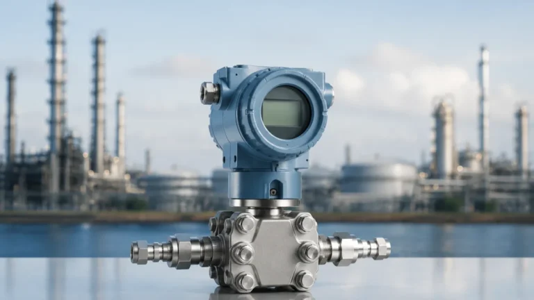
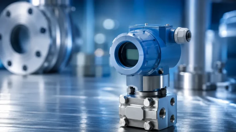
2 Float Level Controller Fret Switch
2 Float Level Controller Fret Switch
In industrial liquid management, maintaining precise control over tank levels is critical for both operational efficiency and safety. The 2 float level controller fret switch is a fundamental component in automated systems, providing a reliable method for monitoring and controlling liquid levels. By utilizing two distinct floats on a single stem or within a coordinated system, engineers can implement complex logic such as pump automation, overflow prevention, and dry-run protection.
This guide examines the technical principles, selection criteria, and installation requirements for dual-float switching systems, specifically focusing on the magnetic reed switch (often referred to in specific technical contexts as a fret switch) mechanism that powers these devices.
Understanding the Measurement Principle
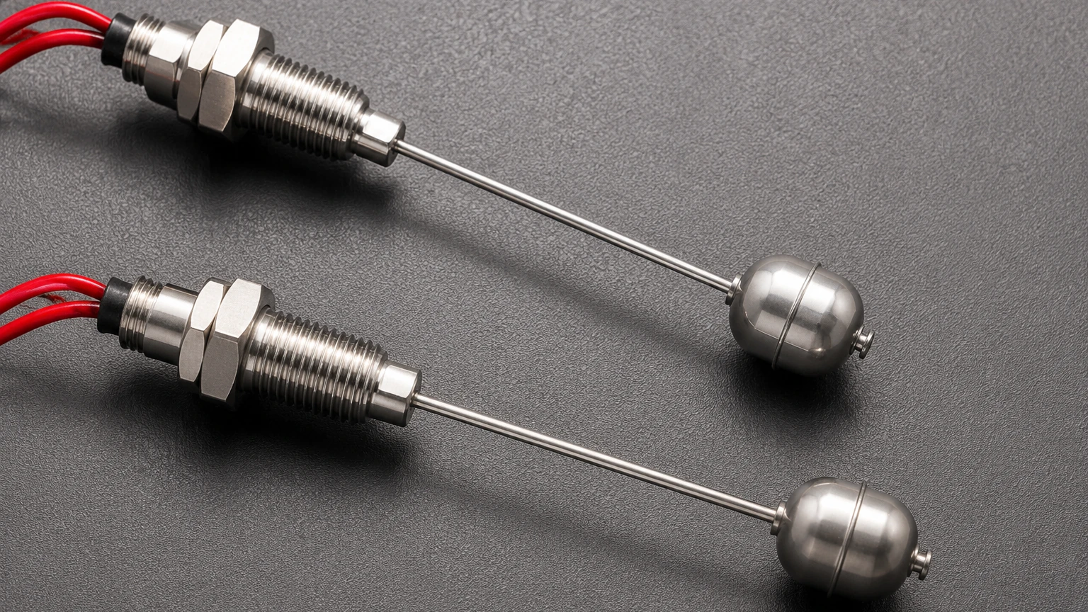
The operation of a 2 float level controller fret switch is based on the principle of magnetic induction. The device typically consists of a hollow stationary stem containing one or more hermetically sealed reed switches (the "fret" components). These reed switches are positioned at specific heights corresponding to the desired activation points.
Inside each buoyant float is a permanent magnet. As the liquid level rises or falls, the float moves along the stem. When the float’s magnetic field reaches the precise location of the internal reed switch, the magnetic force pulls the switch’s contact blades together (closing the circuit) or pushes them apart (opening the circuit).
The "Fret" Switch Mechanism
The term "fret switch" in this context refers to the discrete switching points or the internal contact assembly within the probe. Unlike continuous level sensors that provide a 4-20mA signal, these switches provide point-level detection. Because the switching elements are sealed in an inert gas environment within the stem, they are protected from oxidation, moisture, and the process media, ensuring a long operational lifespan even in harsh chemical environments.
System Configuration: The Role of Dual Floats
While a single-point float switch can signal a high or low alarm, a 2 float level controller fret switch allows for differential control. This is essential for applications like pump control, where a pump must turn on at one level and stay on until a second level is reached.
1. Pump Down (Emptying) Logic
In a drainage or sump application, the system is designed to empty a tank.
* High Level (Float 1): When the liquid reaches the upper float, the switch triggers the pump to start.
* Low Level (Float 2): As the pump lowers the liquid level, the pump continues to run until the liquid reaches the lower float, which then signals the pump to stop.
2. Pump Up (Filling) Logic
In storage tank applications, the goal is to keep the tank full.
* Low Level (Float 2): When the liquid drops below the lower float, the switch activates a fill valve or pump.
* High Level (Float 1): Once the liquid reaches the upper float, the circuit is broken, stopping the filling process to prevent overflow.
Technical Specifications and Selection Criteria
Choosing the correct 2 float level controller fret switch requires an analysis of the fluid properties and the physical environment of the tank. The following table provides a comparison of common materials used in these controllers:
| Material | Temperature Range | Max Pressure | Chemical Compatibility | Typical Application |
| :— | :— | :— | :— | :— |
| Stainless Steel (304/316L) | -20°C to +200°C | 3.0 MPa (30 bar) | High | Oil, high-temp water, food processing |
| Polypropylene (PP) | -10°C to +80°C | 0.5 MPa (5 bar) | Good | Water treatment, mild acids, detergents |
| PVDF (Kynar) | -20°C to +120°C | 1.0 MPa (10 bar) | Excellent | Concentrated acids, aggressive solvents |
| NBR (Buna-N) Float | -10°C to +100°C | 1.5 MPa (15 bar) | Moderate | Fuel tanks, hydraulic oil reservoirs |
Key Evaluation Factors
1. Specific Gravity: The float must be less dense than the liquid it is measuring. For standard water applications (SG 1.0), most floats work well. For light oils (SG 0.7), specialized low-density floats are required.
2. Viscosity: High-viscosity liquids can cause "sticking," where the float fails to move freely along the stem. If the liquid is prone to crystallization or coating, a non-contact method like an ultrasonic level sensor may be more appropriate.
3. Electrical Load: Reed switches are designed for low-current signaling. To control a high-power pump motor, the 2 float level controller fret switch must be connected to a relay or a PLC (Programmable Logic Controller).
Installation Considerations
Proper installation is vital to ensure the accuracy and longevity of the level controller. Engineers should adhere to the following guidelines:
* Vertical Alignment: Most 2 float level controllers must be installed vertically. A tilt of more than 15 to 20 degrees can increase friction between the float and the stem, leading to inconsistent switching.
* Avoid Turbulence: If the tank has an agitator or high-velocity inflow, the resulting turbulence can cause the floats to bounce, leading to "chatter" in the electrical circuit. In such cases, the switch should be installed inside a stilling well (a perforated pipe that stabilizes the liquid surface around the sensor).
* Magnetic Interference: Since the device relies on magnetic fields, it should be kept away from strong external magnetic sources or large ferrous metal structures that could distort the magnetic field and cause false triggering.
* Wiring and Protection: Use shielded cables for long-distance signal transmission to prevent EMI (Electromagnetic Interference). Ensure the junction box is rated for the environment (e.g., IP65 or IP68 for wet areas).
Limitations and Risks
While the 2 float level controller fret switch is a robust and economical solution, it is not suitable for every application.
* Mechanical Wear: Because it is a moving-part sensor, it is subject to mechanical wear over millions of cycles.
* Debris Accumulation: Magnetic particles in the fluid can adhere to the float’s internal magnet, eventually weighing it down or jamming it against the stem. In systems with metallic debris, magnetic filters should be installed upstream.
* Single-Point Failure: If a float becomes punctured and loses buoyancy, it will remain at the bottom of the stem, potentially failing to trigger a critical high-level alarm.
Frequently Asked Questions (FAQ)
Q: Can I adjust the switching points after installation?
A: For most fixed-stem 2 float controllers, the switching points are set during manufacturing and cannot be changed. However, some modular designs allow the user to slide the reed switch assemblies inside the stem to adjust the levels.
Q: What is the difference between NO and NC contacts?
A: NO (Normally Open) means the circuit is open when the float is at the bottom. NC (Normally Closed) means the circuit is closed. Most industrial controllers allow you to reverse the logic by simply flipping the float upside down on the stem.
Q: How do I test if the fret switch is functioning?
A: With the power disconnected, use a multimeter set to resistance (Ohms). Manually slide the float up and down the stem. You should see the resistance drop to near zero when the float passes the switch point and return to infinity when it moves away.
Conclusion
The 2 float level controller fret switch remains a staple in industrial automation due to its simplicity, reliability, and cost-effectiveness. By understanding the material compatibility and mechanical requirements of the application, engineers can implement a level control system that requires minimal maintenance while providing high operational security. For complex projects requiring integration with broader automation suites, it is often beneficial to Review product options and application support on the Welk Main Page to ensure the selected hardware meets all regulatory and technical standards.