In-line Flow Sensor
In-line Flow Sensor
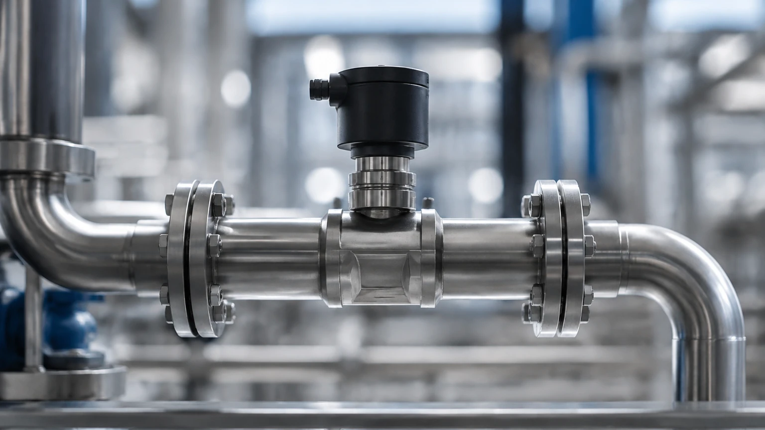
In industrial process control, the accurate measurement of fluid movement is as critical as monitoring the contents of a storage vessel. An in-line flow sensor is a device installed directly into a piping system to measure the flow rate of liquids, gases, or steam. Unlike non-invasive methods, in-line sensors become a physical part of the conduit, ensuring that the sensing elements are in direct contact with or in close proximity to the media. This configuration is essential for high-precision applications in water treatment, chemical processing, and oil and gas automation.
Understanding the specific measurement principles, installation requirements, and selection criteria is vital for engineers tasked with designing efficient systems. While many facilities focus heavily on tank inventory via the Main Page, the integration of flow data allows for comprehensive mass balance and leak detection across the entire plant infrastructure.
Measurement Principles of In-line Flow Sensors
Before selecting a sensor, it is necessary to understand the physics governing different measurement technologies. In-line flow sensors are categorized by the method they use to interpret fluid velocity or mass.
Electromagnetic Flow Meters (Magmeters)
Electromagnetic sensors operate based on Faraday’s Law of Induction. When a conductive liquid flows through a magnetic field generated by the sensor, it produces a voltage proportional to its velocity.
- Requirement: The fluid must have a minimum conductivity (typically >5 μS/cm).
- Benefit: Since there are no moving parts or obstructions in the flow path, there is no pressure drop, and the sensor is highly resistant to wear from slurries.
Ultrasonic In-line Sensors (Transit-Time)
In-line ultrasonic sensors use transducers mounted within the sensor body to send and receive acoustic signals. In the transit-time method, signals are sent upstream and downstream. The difference in time taken for the signal to travel between the two points is directly proportional to the flow velocity.
- Requirement: Best suited for clean liquids with minimal aeration or suspended solids.
- Benefit: High accuracy over a wide turndown ratio.
Vortex Shedding Sensors
These sensors utilize the Von Kármán effect. An obstruction (bluff body) is placed in the flow stream, creating alternating vortices. The frequency at which these vortices are shed is proportional to the flow velocity.
- Requirement: Requires a minimum Reynolds number to ensure stable vortex formation.
- Benefit: Excellent for measuring steam and high-temperature gases.
Turbine Flow Sensors
Turbine sensors feature a rotor that spins as fluid passes through the internal chamber. The rotational speed of the blades is sensed by a magnetic pickup or optical sensor outside the pressure boundary.
- Requirement: Fluid must be clean to prevent damage to bearings or rotor blades.
- Benefit: Very high precision for low-viscosity fluids like fuels and deionized water.
Thermal Mass Flow Sensors
These sensors measure the rate of heat dissipation from a heated element into the fluid stream. The amount of heat lost is a function of the mass flow rate of the gas.
- Requirement: Primarily used for gas applications; requires dry, clean gas for consistent results.
- Benefit: Measures mass flow directly without the need for separate pressure or temperature compensation.
Practical Selection Criteria
Choosing the correct in-line flow sensor requires an evaluation of the fluid properties and the operational environment. The following table provides a comparison of common technologies used in B2B industrial environments.
| Technology | Typical Accuracy | Fluid Types | Pressure Drop | Moving Parts |
| :— | :— | :— | :— | :— |
| Electromagnetic | ±0.5% | Conductive Liquids | Negligible | No |
| Ultrasonic | ±1.0% | Clean Liquids | Negligible | No |
| Vortex | ±1.0% | Gas, Steam, Liquid | Moderate | No |
| Turbine | ±0.25% | Clean, Low-Viscosity | High | Yes |
| Thermal Mass | ±1.0% | Gases | Low | No |
Key Evaluation Factors
1. Fluid Phase and Composition: Determine if the media is liquid, gas, or steam. For liquids, check for conductivity and the presence of solids (slurries).
2. Flow Range (Turndown Ratio): The ratio between the maximum and minimum flow the sensor can accurately measure. Turbine and ultrasonic sensors typically offer higher turndown ratios.
3. Pipe Size and Material: In-line sensors are sized to match the internal diameter (ID) of the piping. Standard sizes range from DN15 (1/2") to DN2000 (80") or larger.
4. Process Conditions: Ensure the sensor body and liner materials (e.g., PTFE, PFA, or Stainless Steel) are compatible with the process temperature and pressure. Standard industrial ratings often reach 16 bar (232 psi) to 40 bar (580 psi).
Installation Considerations and Best Practices
The performance of an in-line flow sensor is heavily dependent on the hydraulic conditions at the point of installation. Disturbed flow profiles caused by elbows, valves, or pumps can introduce significant errors.
Straight Pipe Requirements
Most in-line sensors require a "straight run" of pipe before and after the unit to ensure a fully developed, laminar flow profile.
- Upstream: Typically 10 to 20 pipe diameters (10D – 20D).
- Downstream: Typically 3 to 5 pipe diameters (3D – 5D).
If space is limited, flow conditioners or specific "zero-bore" electromagnetic meters may be required.
Orientation and Mounting
- Vertical Upward Flow: This is the preferred orientation for liquid applications as it ensures the pipe remains completely full, preventing air pockets that could cause measurement drift.
- Horizontal Mounting: Sensors should be installed at the lowest point of a pipe run rather than the highest to avoid gas entrapment. For electromagnetic sensors, electrodes should be positioned horizontally (3 o'clock and 9 o'clock) to prevent interference from sediment or air bubbles.
Grounding and Shielding
For electromagnetic flow sensors, proper grounding is critical. The sensor must be at the same electrical potential as the fluid. In plastic or lined piping systems, grounding rings are necessary to establish this electrical connection. Failure to ground correctly will result in "noise" and unstable readings.
Integration with Level Measurement Systems
In many industrial applications, flow measurement and level measurement are complementary. For example, in a chemical dosing tank, an ultrasonic level sensor monitors the inventory while an in-line flow sensor measures the exact amount of chemical being discharged into the process.
By comparing the change in volume (level) over time with the integrated flow rate (totalizer), engineers can verify the accuracy of both instruments. This redundancy is a cornerstone of safety-instrumented systems (SIS). For more information on coordinating these technologies, refer to the technical resources on the Main Page.
Common Risks and Limitations
Despite their accuracy, in-line flow sensors are subject to specific operational risks that must be managed:
* Cavitation: If the pressure drops below the fluid's vapor pressure (often due to a control valve placed too close to the sensor), bubbles will form. This can cause physical damage to turbine blades and lead to significant measurement errors in ultrasonic and electromagnetic meters.
* Scaling and Coating: In wastewater or chemical crystallization processes, material may build up on the sensor walls or electrodes. This changes the internal diameter or insulates the electrodes, leading to a loss of signal.
* Viscosity Sensitivity: Mechanical meters like turbines are highly sensitive to changes in viscosity. A sensor calibrated for water will not provide accurate readings for heavy oil without a viscosity correction factor.
* Pressure Drop: Unlike level sensors which are often non-contact, in-line flow sensors (especially vortex and turbine types) introduce a pressure drop into the system. This must be accounted for in pump sizing and system head calculations.
Frequently Asked Questions (FAQ)
Q: Can an in-line flow sensor measure flow in both directions?
A: Many modern electromagnetic and ultrasonic sensors are bi-directional. However, they must be configured in the software to track forward and reverse flow separately. Mechanical sensors like turbines are generally uni-directional.
Q: How often should an in-line flow sensor be calibrated?
A: For standard industrial water applications, a 2-year calibration cycle is common. In regulated industries like pharmaceuticals or custody transfer of oil, annual or even semi-annual calibration is often required to maintain compliance.
Q: What happens if the pipe is only partially full?
A: Most in-line flow sensors will fail or provide highly inaccurate data if the pipe is not 100% full. If partial-fill conditions are expected, specialized "partially filled pipe" electromagnetic meters or area-velocity sensors must be used.
Q: Do in-line flow sensors require a power supply?
A: Yes, most industrial in-line sensors require a 24V DC or 110/220V AC power source. While some battery-powered units exist for remote water monitoring, they typically have slower sampling rates to conserve energy.
Conclusion
The in-line flow sensor is a fundamental component of modern industrial automation. By selecting the appropriate measurement principle—whether electromagnetic for conductive liquids or vortex for steam—and adhering to strict installation guidelines regarding straight pipe runs and grounding, operators can achieve reliable and repeatable data. When integrated with advanced level monitoring solutions available at the Main Page, these sensors provide the transparency needed to optimize process efficiency and ensure environmental compliance.