Sewage Lift Stations
Sewage Lift Stations
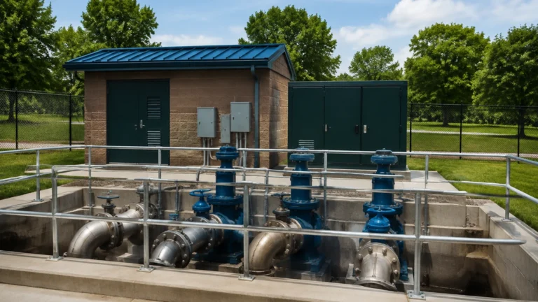
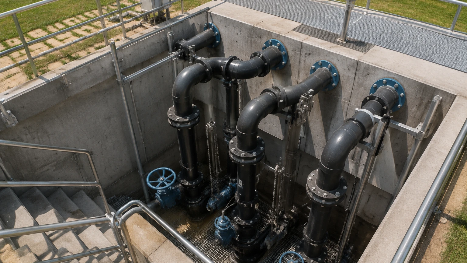
Sewage lift stations, often referred to as pump stations, are critical infrastructure components within municipal and industrial wastewater management systems. Their primary function is to transport wastewater from lower elevations to higher elevations when gravity-fed piping is not geologically or economically feasible. Because these stations handle raw sewage, stormwater runoff, and industrial effluent, they operate in harsh environments characterized by turbulence, corrosive gases, and heavy solids loading.
Reliable operation of a lift station depends almost entirely on accurate level measurement. If a level sensor fails, the station risks pump cavitation due to dry running or, conversely, environmental disasters caused by wet well overflows. This guide provides a technical overview of the technologies used in sewage lift stations, selection criteria, and engineering best practices for installation and maintenance.
The Role of Level Control in Sewage Lift Stations
In a typical lift station configuration, wastewater flows into a wet well. As the liquid level rises, sensors trigger the activation of one or more pumps to move the fluid to a gravity sewer or a treatment facility. The level control system usually manages several setpoints:
1. Low Level (Pump Off): Prevents the pump from drawing air, which causes cavitation and mechanical damage.
2. Lead Pump Start: Activates the primary pump to begin the discharge cycle.
3. Lag Pump Start: Activates a secondary pump if the inflow exceeds the capacity of a single pump.
4. High-Level Alarm: Signals an impending overflow condition, often triggering emergency protocols or telemetry alerts.
Achieving precision across these setpoints requires an understanding of the physical principles governing different measurement technologies.
Measurement Principles for Wastewater Environments
Level measurement in sewage lift stations is generally divided into two categories: contacting and non-contacting technologies. Each operates on distinct physical principles.
Ultrasonic (Non-Contacting)
Ultrasonic sensors emit high-frequency sound pulses that travel through the air, reflect off the liquid surface, and return to the transducer. The sensor calculates the distance based on the "time-of-flight" and the speed of sound.
* Principle: $Distance = (Speed of Sound \times Time) / 2$.
* Application in Sewage: Because the speed of sound is affected by air temperature, these sensors typically include integrated temperature compensation. They are popular due to their lack of moving parts and the fact that they do not touch the corrosive medium.
Radar (Non-Contacting)
Radar level meters utilize electromagnetic (microwave) pulses rather than sound waves. Like ultrasonic sensors, they use time-of-flight to determine distance.
* Principle: Microwaves travel at the speed of light and are largely unaffected by air temperature, pressure, or the presence of heavy vapors like Hydrogen Sulfide ($H_2S$).
* Application in Sewage: Radar is increasingly preferred for lift stations that experience heavy steam or surface foam, as microwaves can penetrate these layers more effectively than sound waves.
Hydrostatic Pressure (Contacting)
Hydrostatic transmitters are submersible pressure sensors placed at the bottom of the wet well. They measure the pressure exerted by the column of liquid above them.
* Principle: $P = \rho gh$, where $P$ is pressure, $\rho$ is fluid density, $g$ is gravity, and $h$ is the height of the liquid.
* Application in Sewage: These sensors are highly accurate for deep wells. However, because they are in constant contact with the sewage, they must be designed with large, flush diaphragms to prevent clogging from solids and grease.
Float Switches (Point Level)
Float switches are mechanical devices that contain an internal microswitch or mercury tilt switch. As the liquid level rises, the float tips, opening or closing a circuit.
* Principle: Buoyancy-driven mechanical actuation.
* Application in Sewage: While less sophisticated than continuous transmitters, floats are essential as redundant high-level alarms because they operate independently of the primary control system.
Comparative Analysis of Level Sensing Technologies
Selecting the appropriate technology requires balancing cost, maintenance requirements, and the specific characteristics of the wastewater. For a broader look at available instrumentation, engineers can refer to the Main Page of professional equipment manufacturers to compare specific model ratings.
| Technology | Accuracy | Maintenance | Ideal Conditions | Limitations |
| :— | :— | :— | :— | :— |
| Ultrasonic | $\pm$ 0.25% | Low | Standard municipal wet wells | Sensitive to heavy foam and steam |
| Radar | $\pm$ 2 mm | Very Low | Industrial sewage, high vapor | Higher initial investment |
| Hydrostatic | $\pm$ 0.1% | Moderate | Deep wells, narrow shafts | Affected by density changes; prone to ragging |
| Float Switch | N/A (Point) | High | Redundant backup/alarms | Prone to grease buildup and mechanical failure |
Engineering Installation Considerations
Proper installation is as critical as sensor selection. In sewage lift stations, the physical environment is often turbulent and confined.
Positioning and Mounting
* Avoid Turbulence: Sensors should not be mounted directly above the influent pipe or near the pump intake. Turbulence and splashing can cause erratic readings in ultrasonic and radar sensors and may cause physical damage to hydrostatic cables.
* Beam Angle: For ultrasonic and radar units, the "beam angle" must be considered. The sensor must have a clear line of sight to the liquid surface, free from obstructions like ladders, pipes, or pump supports. If an obstruction is within the beam, it may cause a "false echo."
* Dead Zone: All non-contact sensors have a "dead zone" or "blocking distance" (typically 0.25 m to 0.5 m) directly below the transducer where measurement is impossible. The sensor must be mounted high enough to account for the maximum possible liquid level.
Stilling Wells
In extremely turbulent wells, a stilling well (a vertical pipe with vent holes) can be installed. This provides a calm surface for non-contact sensors and protects hydrostatic transmitters from the mechanical force of moving water. However, in raw sewage applications, stilling wells can trap grease and debris, necessitating frequent cleaning.
Hazardous Area Classifications
Sewage lift stations are often classified as hazardous locations (e.g., ATEX Zone 0 or 1, or Class I, Div 1) due to the potential for methane and $H_2S$ accumulation. All instrumentation must carry the appropriate explosion-proof or intrinsically safe certifications.
Overcoming Operational Limitations and Challenges
Fats, Oils, and Grease (FOG)
FOG is a significant challenge in sewage applications. Grease tends to accumulate on any surface it touches. For hydrostatic sensors, this can coat the diaphragm and lead to measurement drift. For float switches, grease can become so thick that it prevents the float from tipping. Non-contact sensors (Radar/Ultrasonic) are generally superior in high-FOG environments because they do not touch the medium.
Foam and Surface Agitation
Foam is a common byproduct of detergents and biological activity in wastewater. Ultrasonic waves are often absorbed or scattered by foam, leading to a "lost echo" signal. Radar is more resilient, but extremely thick, dense foam may still require the use of a higher-frequency radar or a stilling well.
Corrosive Gases
Hydrogen Sulfide ($H_2S$) is not only toxic but also highly corrosive to electronics and copper wiring. Sensors used in lift stations should feature housings made of corrosion-resistant materials such as PVDF, 316L Stainless Steel, or specialized plastics. Cable jackets should be made of Polyurethane (PUR) or FEP to prevent degradation.
Maintenance and Troubleshooting Protocols
Even the most advanced sensors require a structured maintenance program to ensure long-term reliability in sewage lift stations.
1. Visual Inspection: Monthly checks for grease accumulation on floats or the faces of ultrasonic transducers. A simple wipe-down can prevent signal loss.
2. Calibration Verification: Annual verification of the sensor's accuracy against a physical measurement (e.g., a manual tape measure). For hydrostatic sensors, this is critical as the sensor may drift over time due to diaphragm fatigue.
3. Venting Check: Hydrostatic transmitters use a small vent tube in their cable to compensate for changes in atmospheric pressure. If this tube becomes blocked or moisture enters it, the readings will be inaccurate. Desiccant cartridges at the end of the vent tube should be replaced regularly.
4. Signal Monitoring: Modern digital sensors (using HART or Modbus) can provide diagnostic data, such as signal strength. A declining signal strength in an ultrasonic sensor often indicates a buildup of condensation or grease on the transducer face.
Frequently Asked Questions (FAQs)
Q: Can I use an ultrasonic sensor in a wet well with heavy steam?
A: Steam can change the speed of sound and cause condensation on the transducer face, both of which degrade ultrasonic performance. In such cases, a non-contact radar sensor is a more reliable choice as it is unaffected by gas composition.
Q: How do I prevent "ragging" on my hydrostatic sensor?
A: Ragging occurs when fibrous materials in sewage wrap around the sensor or its cable. Using a flush-diaphragm sensor and mounting it inside a protective cage or a large-diameter stilling well can mitigate this issue.
Q: What is the benefit of using a dual-sensor setup?
A: Many critical lift stations use a "redundant" setup, such as an ultrasonic transmitter for continuous control and a float switch for a high-level alarm. This ensures that if the primary electronic system fails, a mechanical backup is available to prevent an overflow.
Q: How does fluid density affect hydrostatic level measurement?
A: Hydrostatic sensors measure pressure, which is a function of density. If the sewage has a high concentration of solids or if the density changes significantly (e.g., during heavy rain events), the sensor may report a slightly different level than the actual height. In most municipal applications, this error is negligible, but it should be considered in industrial wastewater.
By understanding these technical nuances, engineers can design more resilient sewage lift stations that minimize environmental risk and reduce long-term operational costs. For detailed product specifications and selection support, visiting the Main Page of an industrial instrument provider is recommended to ensure the hardware meets the specific demands of the site.