Waste Water Lift Station
Waste Water Lift Station
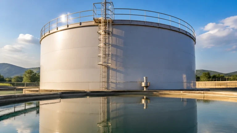
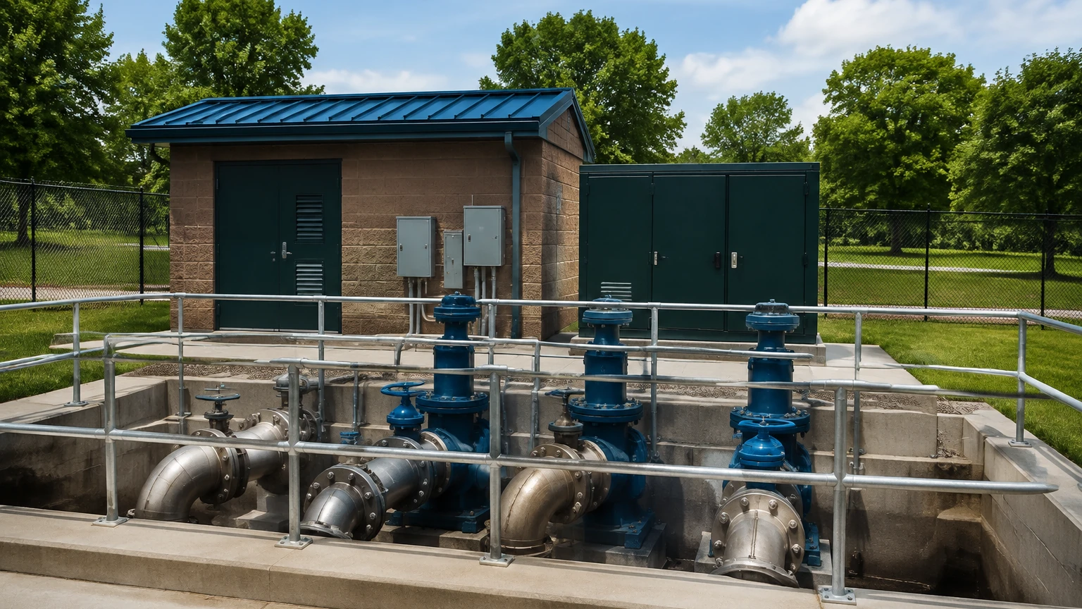
A waste water lift station, often referred to as a pumping station, is a critical infrastructure component designed to move wastewater from lower to higher elevations. In municipal and industrial sewage systems, gravity is the primary force used to transport effluent. However, when the terrain is flat, hilly, or when the destination treatment plant is at a higher elevation than the source, gravity flow becomes impossible. The lift station provides the necessary energy to overcome these topographical challenges.
The heart of an effective waste water lift station is its control system, which relies heavily on accurate and reliable level measurement. Because these stations often operate in remote locations and handle corrosive, debris-laden fluids, the choice of instrumentation is paramount for preventing overflows and optimizing pump life. This guide explores the engineering principles of level measurement within lift stations and provides practical selection and installation criteria.
Core Level Measurement Principles for Lift Stations
Before selecting a specific instrument for a waste water lift station, it is essential to understand the physical principles that govern different measurement technologies. In a typical wet well environment, three primary methods are used: hydrostatic pressure, ultrasonic time-of-flight, and radar (microwave) time-of-flight.
Hydrostatic Level Measurement
Hydrostatic measurement is based on the principle that the pressure at a specific point in a static liquid is proportional to the height of the liquid column above it. The relationship is defined by the formula:
P = ρ × g × h
Where:
* P is the hydrostatic pressure (Pascals).
* ρ (rho) is the density of the wastewater (kg/m³).
* g is the acceleration due to gravity (approximately 9.81 m/s²).
* h is the height of the liquid (meters).
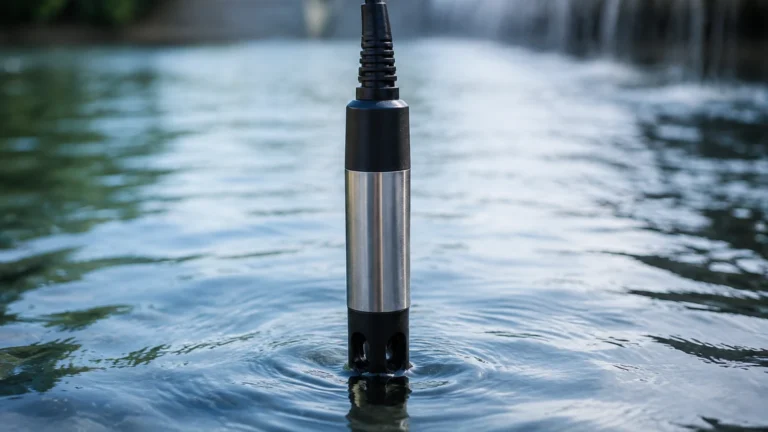
In a lift station, a submersible pressure transmitter is lowered to the bottom of the wet well. The sensor measures the total pressure (liquid pressure + atmospheric pressure). To provide an accurate level reading, the transmitter uses a vented cable to compensate for changes in atmospheric pressure. This technology is valued for its simplicity and direct contact measurement, though it is susceptible to errors if the density of the wastewater changes significantly due to heavy sediment or chemical influx.
Ultrasonic Level Measurement
Ultrasonic sensors are non-contact devices that emit high-frequency sound pulses (typically 20 kHz to 60 kHz). These pulses travel through the air, reflect off the surface of the wastewater, and return to the sensor. The distance is calculated based on the time it takes for the echo to return:
Distance = (Speed of Sound × Time) / 2
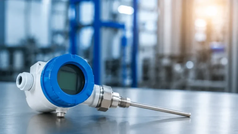
Because the speed of sound is affected by air temperature, most industrial ultrasonic sensors include an integrated temperature probe to compensate for these variations. Ultrasonic sensors are popular because they do not touch the corrosive wastewater, reducing maintenance needs related to sensor fouling.
Radar Level Measurement
Radar level measurement operates similarly to ultrasonic technology but uses electromagnetic waves (microwaves) instead of sound waves. These waves travel at the speed of light and are unaffected by air temperature, pressure, or the presence of vapors and gases like Hydrogen Sulfide (H2S).
Modern 80 GHz high-frequency radar sensors are particularly effective in a waste water lift station because they offer a very narrow beam angle. This allows the signal to avoid internal obstructions such as ladders, pipes, and pump supports that often cause false echoes in older radar or ultrasonic systems.
Point Level Detection (Secondary Control)
In addition to continuous level measurement, most lift stations utilize point level detection for redundant high-level alarms or low-level pump protection.
1. Float Switches: These are mechanical switches encased in a buoyant housing. As the water rises, the float tilts, triggering a microswitch. While inexpensive, they are prone to "ragging" (entanglement with debris) and grease buildup.
2. Conductivity Probes: These detect the presence of liquid by measuring the electrical conductivity between two electrodes. They are robust but can fail if a thick layer of non-conductive grease coats the probes.
Selection Criteria: Matching Technology to Environment
Choosing the right instrument for a waste water lift station requires an assessment of the specific environment. Factors such as the presence of foam, the concentration of grease, and the physical dimensions of the wet well play a decisive role.
Instrument Selection Table for Lift Station Applications
| Technology | Typical Accuracy | Maintenance Needs | Best For | Limitations |
| :— | :— | :— | :— | :— |
| Hydrostatic | ±0.1% to ±0.5% | Moderate (cleaning) | Deep wells, stable density | Sensitive to sludge buildup |
| Ultrasonic | ±0.25% | Low | Standard municipal wells | Blocked by heavy foam/steam |
| Radar (80 GHz) | ±2 mm | Minimal | Narrow wells, foaming liquids | Higher initial investment |
| Float Switches | N/A (Point) | High (cleaning) | Redundant high/low alarms | Prone to mechanical failure |
For engineers looking to optimize their systems, reviewing professional Main Page resources can provide deeper insights into specific product specifications and OEM/ODM customization options for harsh environments.
Installation Best Practices and Engineering Considerations
Proper installation is as critical as sensor selection. Even the most advanced radar sensor will fail if it is positioned incorrectly within the waste water lift station.
1. Avoiding Turbulence and Inflow
Sensors should never be installed directly under an inflow pipe. The turbulence and splashing will cause erratic readings. For hydrostatic sensors, if the well is highly turbulent, a stilling well (a perforated pipe) should be used to protect the sensor and stabilize the liquid column.
2. Beam Angle and Obstructions
For non-contact sensors (ultrasonic and radar), the "beam cone" must be kept clear of obstructions. If a sensor is mounted too close to a wall, the signal may reflect off the concrete rather than the water.
* Ultrasonic: Typically requires a wider clearance.
* Radar (80 GHz): Can be installed in very tight spaces due to its narrow 3-degree beam.
3. The "Dead Zone" or Blocking Distance
All non-contact sensors have a minimum distance they cannot measure, known as the dead zone or blocking distance. The sensor must be mounted high enough so that the maximum possible water level never enters this zone. If the water reaches the sensor face, the reading will typically lock at the maximum or jump to zero.
4. Chemical Compatibility and H2S Gas
Waste water lift stations are notorious for high levels of Hydrogen Sulfide (H2S), which reacts with moisture to form sulfuric acid. All exposed instrumentation must be constructed from corrosion-resistant materials.
* Sensor Bodies: PVDF, PP, or 316L Stainless Steel are preferred.
* Cables: Polyurethane (PUR) or FEP cables are recommended for hydrostatic sensors to prevent chemical permeation.
Operational Risks and Limitations
Operating a waste water lift station involves managing several inherent risks that can interfere with level instrumentation:
* Grease and FOG (Fats, Oils, and Grease): In many municipal systems, grease accumulates at the top of the wet well. This can coat hydrostatic diaphragms or create a "false floor" for ultrasonic signals. Radar is generally the most resistant to grease layers.
* Foam: Heavy foam, often caused by detergents or biological activity, absorbs ultrasonic sound waves, leading to a "loss of echo." Radar is better at penetrating foam, though extremely dense, thick foam may still attenuate the signal.
* Lightning and Surges: Lift stations are often the highest point of electrical conductivity in an area. Submersible sensors are particularly vulnerable to lightning strikes. Integrated surge protection in the transmitter and the control panel is essential.
* Ragging: Debris such as wet wipes and plastic can wrap around submerged cables or float switches, causing physical damage or false triggers.
Frequently Asked Questions (FAQ)
Q: How often should I calibrate the level sensors in a lift station?
A: For ultrasonic and radar sensors, an annual check is usually sufficient. Hydrostatic sensors may require more frequent zero-point checks (every 6 months) if the wastewater has a high sediment content that might coat the diaphragm.
Q: Can I use a radar sensor if there is a lot of steam in the wet well?
A: Yes. Unlike ultrasonic waves, radar electromagnetic waves are not significantly affected by steam or vapor, making radar the superior choice for hot industrial effluent.
Q: What is the benefit of using a 4-20mA signal versus a digital output like Modbus?
A: 4-20mA is the industry standard for its simplicity and ability to travel long distances without signal loss. However, digital protocols like Modbus or HART provide additional diagnostic data (e.g., sensor temperature, signal strength), which is valuable for predictive maintenance.
Q: How do I protect a hydrostatic sensor from "fatbergs"?
A: Use a sensor with a flush ceramic diaphragm rather than a recessed metal one. Ceramic is harder and easier to clean. Additionally, mounting the sensor slightly off the bottom of the well prevents it from being buried in heavy sludge.
Conclusion
Reliable operation of a waste water lift station hinges on selecting level measurement technology that matches the specific challenges of the site. While ultrasonic sensors remain a cost-effective standard for many applications, the declining cost and high precision of 80 GHz radar make it an increasingly popular choice for problematic wells. Hydrostatic transmitters continue to offer a robust solution for deep wells where non-contact mounting is impractical. By adhering to strict installation guidelines and considering the chemical and physical nature of the effluent, engineers can ensure long-term accuracy and prevent costly environmental incidents. For further technical specifications and to explore a wide range of industrial level measurement solutions, professionals are encouraged to Review product options and application support to find the ideal fit for their infrastructure needs.