Inline Flow Transmitter
Inline Flow Transmitter
In the landscape of industrial process control, the inline flow transmitter serves as a fundamental sensory component, providing real-time data on the movement of liquids, gases, and steam within a piping system. Unlike non-invasive methods, an inline flow transmitter is integrated directly into the process line, ensuring that the sensor remains in constant contact with the media. This direct interaction is critical for achieving high accuracy and repeatability in sectors ranging from chemical processing and water treatment to oil and gas production.
While level measurement instruments—such as those provided by Welk—monitor the volume of inventory within tanks and vessels, the inline flow transmitter monitors the rate at which that inventory is moved. Together, these two technologies form the backbone of mass balance and process efficiency. This guide explores the engineering principles, selection criteria, and installation requirements for inline flow transmitters in professional B2B environments.
Core Measurement Principles of Inline Flow Transmitters
Selecting the correct inline flow transmitter requires a deep understanding of the physical principles used to derive flow velocity or mass. No single technology is universal; each has specific fluid requirements and environmental constraints.
Electromagnetic Flow Measurement (Magmeters)
Electromagnetic transmitters operate on Faraday’s Law of Induction. When a conductive liquid flows through a magnetic field generated by the transmitter, it produces a voltage proportional to its velocity.
- Fluid Requirement: The liquid must have a minimum conductivity (typically >5 μS/cm).
- Advantages: No moving parts, zero pressure drop, and high resistance to corrosive chemicals.
- Common Applications: Wastewater treatment, slurry transport, and chemical dosing.
Ultrasonic Transit-Time Measurement
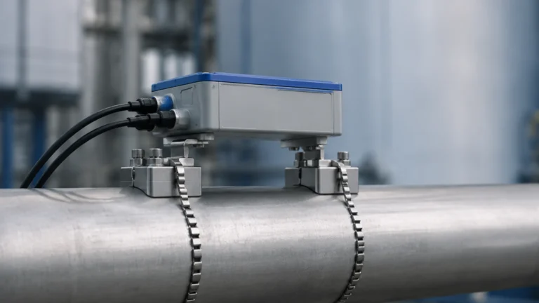
Inline ultrasonic transmitters utilize pairs of transducers to send and receive acoustic signals through the fluid. The difference in time taken for the signal to travel upstream versus downstream is used to calculate flow velocity.
- Fluid Requirement: Best suited for clean, homogeneous liquids with minimal aeration or suspended solids.
- Advantages: Extremely high accuracy and the ability to measure non-conductive fluids like deionized water or hydrocarbons.
Vortex Shedding Principle
Vortex transmitters utilize the Von Kármán effect. A "shedder bar" is placed in the flow path, creating alternating vortices. The frequency of these vortices is directly proportional to the flow velocity.
- Fluid Requirement: Effective for low-viscosity liquids, high-pressure gases, and saturated or superheated steam.
- Advantages: Robust construction with no moving parts; excellent for high-temperature applications (up to 400°C / 752°F).
Turbine and Positive Displacement
These mechanical transmitters use the kinetic energy of the fluid to rotate a turbine or move a set of gears. Each rotation corresponds to a specific volume of fluid.
- Fluid Requirement: Clean, low-viscosity liquids for turbines; high-viscosity oils for positive displacement (PD) meters.
- Advantages: High precision for fiscal metering and custody transfer.
Practical Selection Criteria for Process Engineers
Choosing an inline flow transmitter involves balancing technical performance with total cost of ownership. Engineers must evaluate the chemical compatibility of the wetted parts, the dynamic range (turndown ratio), and the required communication protocols (e.g., 4-20mA HART, Modbus, or Profibus).
Technology Comparison Table
| Technology | Typical Accuracy | Pressure Drop | Fluid Type | Maintenance Needs |
| :— | :— | :— | :— | :— |
| Electromagnetic | ±0.5% | Negligible | Conductive Liquids | Low |
| Ultrasonic (Inline) | ±0.5% to ±1.0% | None | Clean Liquids/Gases | Low |
| Vortex | ±1.0% | Medium | Steam, Gas, Liquid | Medium |
| Turbine | ±0.25% | High | Low Viscosity Liquid | High (Moving parts) |
| Thermal Mass | ±1.0% | Low | Pure Gases | Low |
Process Conditions
1. Pressure and Temperature: Ensure the transmitter housing and gaskets are rated for the maximum process pressure (e.g., 40 bar / 580 psi) and temperature extremes.
2. Viscosity and Density: High-viscosity fluids can cause significant pressure drops in mechanical meters and may dampen the signal in vortex or ultrasonic meters.
3. Corrosivity: For aggressive acids, transmitters with PFA or PTFE liners and Hastelloy electrodes are often required.
Installation Considerations and Best Practices
The performance of an inline flow transmitter is heavily dependent on the hydraulic conditions at the point of installation. Disturbed flow profiles caused by elbows, valves, or pumps can introduce significant measurement errors.
Straight Pipe Requirements
Most inline transmitters require a specific length of straight pipe both upstream and downstream of the sensor to allow the flow profile to stabilize.
- Upstream: Typically 10 to 20 pipe diameters (10D – 20D).
- Downstream: Typically 5 pipe diameters (5D).
If space is restricted, flow conditioners or specific "zero-run" electromagnetic meters may be necessary.
Orientation and Filling
For accurate measurement, the sensor must remain completely full of liquid at all times.
- Vertical Installation: Flow should always move upward. This ensures the pipe remains full and prevents air bubbles from being trapped at the sensor head.
- Horizontal Installation: The transmitter should not be placed at the highest point of a piping system (where air collects) or the lowest point (where sediment collects). In electromagnetic meters, electrodes should be oriented horizontally to prevent insulation by air or interference by solids.
Grounding and Shielding
Particularly for electromagnetic transmitters, proper grounding is essential to eliminate electrical noise. If the piping is plastic or lined, grounding rings must be installed to create a stable electrical reference between the fluid and the transmitter electronics.
Limitations and Environmental Challenges
While highly reliable, inline flow transmitters face specific operational hurdles:
- Cavitation: If the pressure drops below the vapor pressure of the liquid, bubbles form and collapse, causing physical damage to the transmitter and erratic readings.
- Scaling and Coating: In wastewater or chemical applications, material buildup on the internal walls or electrodes can shift the calibration or insulate the sensors. Periodic cleaning or the use of "self-cleaning" electrode designs may be required.
- Reynolds Number Constraints: Technologies like vortex shedding require a minimum Reynolds number (typically >10,000) to maintain a stable shedding frequency. At low flow rates, these meters may drop to a "zero" reading even if flow is present.

Integrating Flow and Level Measurement
In sophisticated industrial automation, an inline flow transmitter rarely works in isolation. It is usually part of a wider control loop that includes level measurement. For instance, in a chemical blending tank, a radar level meter monitors the total volume, while multiple inline flow transmitters control the precise dosage of various reagents.
By comparing the data from the Main Page of your level measurement system with the real-time data from flow transmitters, operators can detect leaks, verify pump performance, and ensure inventory accuracy. This synergy is vital for "loss control" in high-value fluid handling, where even a 0.5% discrepancy can result in significant financial loss over time.
Maintenance and Calibration Protocols
To maintain the integrity of the data, a scheduled maintenance program is necessary.
1. Zero-Point Verification: Periodically checking the transmitter's output under a "no-flow" condition with a full pipe.
2. In-situ Verification: Modern digital transmitters often include internal diagnostic suites that can verify the health of the electronics and sensor coils without removing the device from the line.
3. External Calibration: For regulated industries (e.g., pharmaceutical or food and beverage), the transmitter may need to be removed every 1-3 years for master-meter or gravimetric calibration at a certified laboratory.
Frequently Asked Questions (FAQ)
Q: Can an inline flow transmitter measure bidirectional flow?
A: Yes, many electromagnetic and ultrasonic transmitters are designed to measure flow in both directions, providing separate totals for forward and reverse flow.
Q: What is the difference between an inline flow meter and a flow transmitter?
A: A "meter" typically refers to the entire device, while the "transmitter" specifically refers to the electronic component that converts the sensor's raw signal into a standardized output like 4-20mA or a digital bus signal.
Q: How do I handle flow measurement in pipes with high vibration?
A: Mechanical meters and vortex meters are sensitive to vibration. In such environments, electromagnetic or ultrasonic transmitters are preferred, or specialized vibration-dampening mounts must be used.
Q: Is it possible to measure gas flow with an electromagnetic transmitter?
A: No. Electromagnetic transmitters require a conductive fluid. Gases are non-conductive, so vortex, thermal mass, or ultrasonic technologies must be used instead.
By adhering to these engineering standards and carefully matching the transmitter technology to the process media, facilities can ensure long-term reliability and precise control over their fluid assets.