Fuel Tank Level Gauge Sensor
Fuel Tank Level Gauge Sensor
In industrial operations, the precise monitoring of fuel inventory is a critical factor for both operational efficiency and safety. Whether managing bulk storage for power generation, diesel reserves for data center backup systems, or chemical fuel stocks for manufacturing, selecting the appropriate fuel tank level gauge sensor requires a deep understanding of the underlying measurement physics and the environmental variables of the application.
Fuel measurement is complicated by factors such as vapor pressure, temperature-induced density changes, and the hazardous nature of the media. This guide provides a technical overview of the primary sensing technologies used in modern fuel management and offers an engineering framework for selection and installation.
Measurement Principles and Technologies
Before selecting a sensor, it is essential to understand how different physical principles interact with fuel properties. Fuel tank level gauge sensors generally fall into two categories: contact and non-contact measurement.
1. Radar Level Measurement (FMCW and Pulse)
Radar technology has become the benchmark for high-accuracy fuel measurement. It operates on the Time-of-Flight (ToF) principle, where microwave signals are emitted from the sensor antenna, reflected off the fuel surface, and received back at the sensor.
* Pulse Radar: Sends discrete microwave bursts and measures the time taken for the return. It is effective for many standard applications.
* FMCW (Frequency Modulated Continuous Wave): These sensors, often operating at 26GHz or 80GHz, transmit a continuous signal with a varying frequency. The difference in frequency between the transmitted and received signal is proportional to the distance. 80GHz radar is particularly advantageous for fuel tanks because its narrow beam angle avoids internal obstructions like heating coils or ladders.
Radar is largely unaffected by the vapor space above the fuel, making it ideal for volatile liquids like gasoline or jet fuel. For comprehensive technical specifications on these systems, engineers often consult the Main Page of specialized manufacturers to compare beam angles and dielectric requirements.
2. Ultrasonic Level Sensors
Ultrasonic sensors also use the Time-of-Flight principle but utilize sound waves instead of electromagnetic waves. The sensor emits an ultrasonic pulse (typically 20kHz to 200kHz) that bounces off the fuel surface.
* Limitations: Ultrasonic waves are mechanical and require a medium (air/gas) to travel. Their speed is influenced by air temperature and the composition of the vapor space. In fuel tanks where heavy hydrocarbon vapors are present, the speed of sound changes, which can lead to measurement errors unless temperature compensation and vapor-specific calibration are applied.
3. Hydrostatic Pressure Transmitters
Hydrostatic sensors measure the pressure exerted by the liquid column at the bottom of the tank. The formula used is $P = \rho \cdot g \cdot h$, where $P$ is pressure, $\rho$ (rho) is the density of the fuel, $g$ is gravity, and $h$ is the height of the liquid.
* Implementation: These can be submersible sensors dropped to the bottom or externally mounted pressure transducers at the tank's base.
* Critical Factor: Since the measurement depends on density, any change in fuel temperature that alters the density will affect the level reading. High-precision systems often include an integrated PT100 temperature sensor to perform real-time density correction.
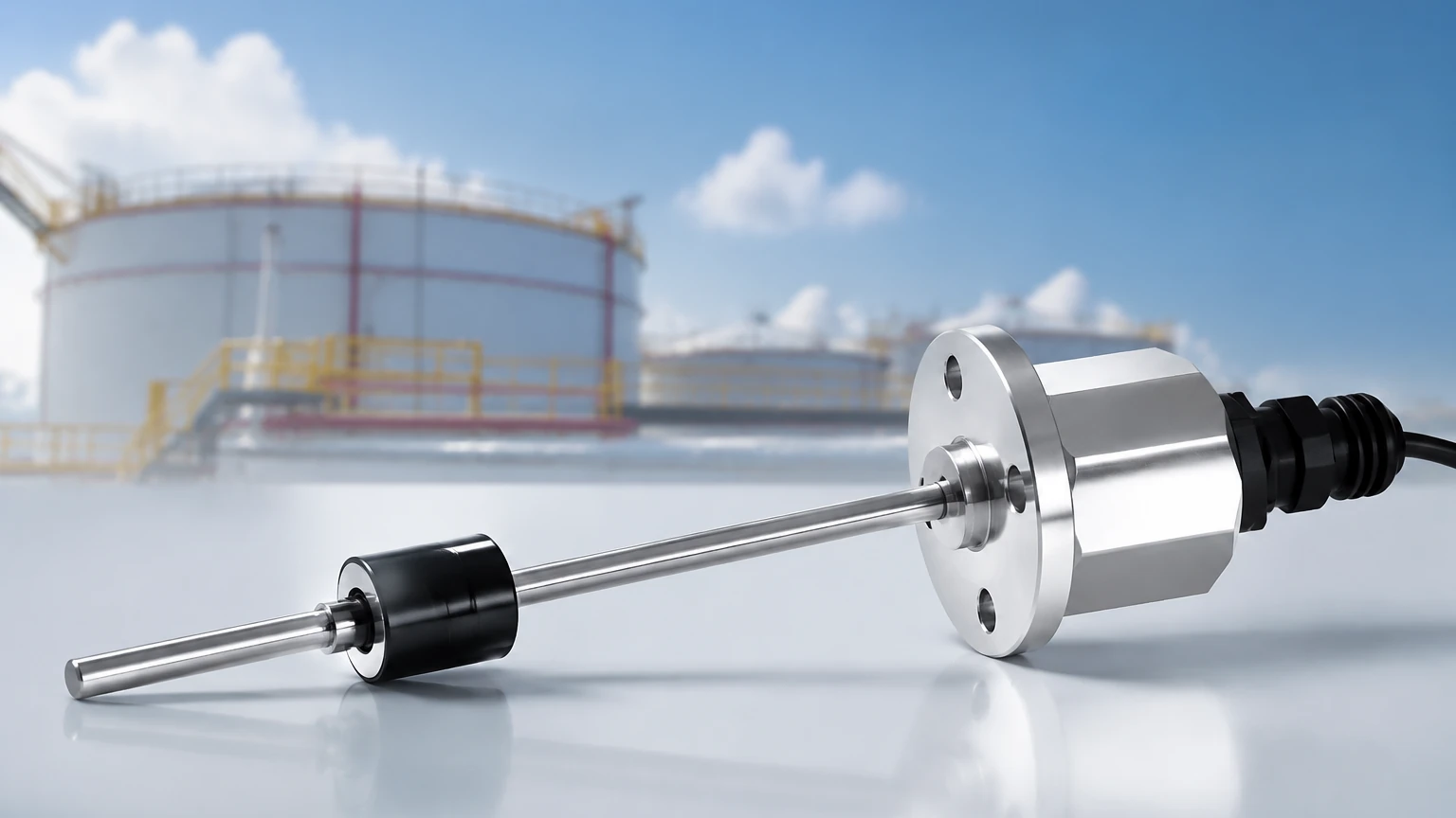
4. Magnetic Level Gauges
Magnetic level gauges are a contact-based solution consisting of a bypass chamber mounted to the side of the tank. Inside the chamber, a float containing a permanent magnet moves with the fuel level. Outside the chamber, a series of magnetic flaps or a transmitter tracks the float’s position.
This method provides both a local visual indication and a remote 4-20mA or RS485 signal. It is highly reliable for pressurized tanks where electronic non-contact sensors might face installation challenges.
5. Capacitance Level Sensors
Capacitance sensors treat the fuel and the vapor space as a dielectric material between two electrodes (usually the sensor probe and the tank wall). As the fuel level rises, the total capacitance of the system changes because the dielectric constant ($ε_r$) of fuel is higher than that of air.
* Usage: Best suited for non-conductive fuels with a stable dielectric constant. If the fuel contains varying levels of water (which has a much higher dielectric constant), the sensor may require frequent recalibration.
Technical Selection Matrix
Choosing the right fuel tank level gauge sensor involves balancing accuracy, cost, and environmental constraints. The following table provides a comparison based on typical industrial requirements.
| Technology | Accuracy | Media Compatibility | Best For | Main Limitation |
| :— | :— | :— | :— | :— |
| 80GHz Radar | ±1 mm | All fuels, including volatile | High-precision custody transfer | Higher initial cost |
| Ultrasonic | ±0.25% of range | Diesel, non-volatile oils | Open-air or vented tanks | Affected by heavy vapors |
| Hydrostatic | ±0.1% to 0.5% | Heavy oils, diesel | Deep underground tanks | Sensitive to density changes |
| Magnetic Gauge | ±5 mm | Most fuels | High-pressure/High-temp tanks | Moving parts require cleaning |
| Capacitance | ±1% | Consistent fuel types | Small tanks/OEM integration | Sensitive to moisture/water |
Installation Considerations for Fuel Environments
Correct installation is as vital as the technology choice. For a fuel tank level gauge sensor to perform within its specified accuracy, several engineering factors must be addressed:
1. The "Dead Zone" or Blocking Distance
Every non-contact sensor (Radar and Ultrasonic) has a near-field region where it cannot accurately process signals. When designing the tank, the sensor must be mounted high enough—often using a nozzle or standpipe—to ensure the fuel level never enters this dead zone, even when the tank is at 100% capacity.
2. Internal Obstructions and Beam Angle
In many fuel tanks, internal structures like agitators, baffles, or heating pipes can create false echoes. Radar sensors with a narrow beam angle (e.g., 3° to 6°) are preferred to steer the signal away from these obstructions. If obstructions are unavoidable, software-based "false echo suppression" must be configured during commissioning.
3. Hazardous Area Classifications
Fuel storage environments are typically classified as Zone 0, 1, or 2 (ATEX/IECEx) or Class I, Div 1/2 (NEC). The fuel tank level gauge sensor must carry the appropriate certification.
* Intrinsically Safe (Ex ia): Limits the energy available for ignition.
* Flameproof (Ex d): Encloses any potential internal explosion within the sensor housing.
4. Mounting Position
Sensors should generally not be mounted in the center of a tank (to avoid multiple reflections from the tank walls) or too close to the fill inlet (where turbulence and foam can interfere with the signal). A position at 1/3 to 1/2 of the tank radius is often optimal.
Limitations and Operational Risks
While modern sensors are robust, certain conditions can compromise their performance:
* Foaming: During high-speed filling, some fuels can foam. Ultrasonic signals are often absorbed by foam, leading to a "loss of echo." Radar is more resistant but can still experience signal attenuation.
* Turbulence: Rapid surface movement can scatter the return signal. In these cases, a stilling well (a pipe that extends to the bottom of the tank to stabilize the liquid surface) is recommended for both radar and ultrasonic sensors.
* Paraffin Wax and Buildup: For heavy crude or fuel oils, wax buildup on contact probes or the faces of ultrasonic transducers can cause drift. Non-contact radar with a PTFE-coated antenna is the preferred solution for sticky or coating media.
Maintenance and Calibration Protocols
To ensure long-term reliability of a fuel tank level gauge sensor, a proactive maintenance schedule is required:
1. Visual Inspection: Check for corrosion on mounting flanges and ensure cable glands remain sealed against moisture ingress.
2. Zero-Point Verification: Periodically compare the sensor reading against a manual dip-tape measurement. This is especially important for hydrostatic sensors where the sensor diaphragm might experience "drift" over time.
3. Signal Strength Monitoring: Modern digital sensors (HART, Modbus) provide diagnostic data regarding signal quality. A drop in signal-to-noise ratio often precedes a total sensor failure, allowing for predictive maintenance.
Frequently Asked Questions (FAQ)
Q: Can I use one sensor for different types of fuel?
A: It depends on the technology. Radar is generally versatile. However, hydrostatic and capacitance sensors must be recalibrated if you switch between fuels with different densities or dielectric constants (e.g., switching from Diesel to Ethanol-blended fuels).
Q: How do I measure fuel level in a horizontal cylindrical tank?
A: The sensor measures the linear distance to the surface. To get the volume, the controller or PLC must apply a strapping table or a mathematical formula to account for the non-linear volume-to-height relationship of a horizontal cylinder.
Q: Is a stilling well necessary for all fuel tanks?
A: No, but it is highly recommended for tanks with high turbulence, heavy foam, or very low dielectric fuels. It acts as a waveguide for radar and a stabilizer for the liquid surface.
Conclusion
Selecting a fuel tank level gauge sensor is a balance of physics and environmental reality. For most industrial fuel applications, 80GHz radar offers the highest reliability and lowest maintenance, while hydrostatic transmitters provide a cost-effective solution for simple diesel storage. When specifying a system, always confirm the hazardous area requirements and the physical properties of the fuel. For detailed product selection and engineering support, professionals often Review product options and application support to ensure the chosen instrument matches the specific demands of their process infrastructure.