Heating Oil Tank Sensor
Heating Oil Tank Sensor
Effective inventory management in industrial and commercial facilities relies heavily on the accuracy of the heating oil tank sensor. Whether managing a single backup generator fuel supply or a complex network of heating systems across a campus, the ability to monitor fuel levels in real-time is critical for operational continuity, environmental safety, and cost control. Modern level measurement technology has evolved significantly from simple mechanical floats to sophisticated electronic sensors that provide high-precision data for automation and logistics.
Selecting the appropriate heating oil tank sensor requires an understanding of the underlying physics of level measurement, the physical properties of the fuel, and the specific constraints of the storage environment. This guide examines the primary measurement principles used in the industry, provides selection criteria for engineering teams, and outlines best practices for installation and maintenance.
Measurement Principles for Heating Oil
Before selecting a sensor, it is essential to understand how different technologies interact with the medium. Heating oil, typically a Grade 2 fuel oil or similar distillate, has specific characteristics—such as viscosity changes with temperature and the potential for vapor accumulation—that influence sensor performance.
Ultrasonic Level Measurement
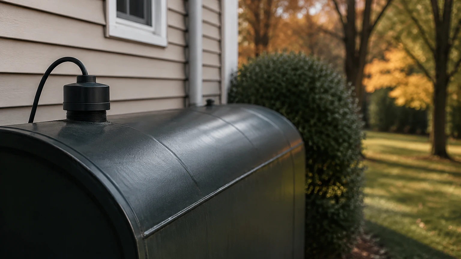
Ultrasonic sensors are among the most common non-contact solutions for heating oil. These devices emit high-frequency sound pulses from a transducer located at the top of the tank. The pulses travel through the air gap, reflect off the surface of the oil, and return to the transducer.
The sensor calculates the distance based on the time-of-flight (ToF) of the sound wave. Because the speed of sound is affected by air temperature, most high-quality ultrasonic sensors include integrated temperature compensation. This technology is ideal for standard atmospheric tanks where the internal environment is relatively stable. However, heavy foam or significant vapor layers can attenuate the signal, leading to inaccuracies.
Hydrostatic Pressure Measurement
Hydrostatic sensors, or submersible pressure transmitters, operate on the principle that the pressure at the bottom of a liquid column is directly proportional to the height of that column and the density of the liquid. The formula used is $P = \rho gh$, where $P$ is pressure, $\rho$ is the density of the oil, $g$ is gravity, and $h$ is the height of the liquid.
These sensors are typically lowered to the bottom of the tank or mounted via a flange at the tank base. They are particularly effective for deep tanks or underground storage where top-access might be limited. One critical consideration for heating oil is that density changes with temperature. For high-precision applications, the system must account for these density fluctuations to maintain accuracy.
Radar (Microwave) Level Measurement
Radar sensors function similarly to ultrasonic sensors but use electromagnetic waves instead of sound. There are two primary types: non-contact (pulsed or FMCW) and guided wave radar (GWR).
Radar is often considered the gold standard for industrial fuel monitoring because electromagnetic waves are unaffected by temperature, pressure, or the presence of vapors in the ullage space. Guided wave radar uses a probe that extends into the oil, directing the signal and providing a very strong reflection even with low-dielectric fluids like heating oil (which typically has a dielectric constant between 2.0 and 2.1).
Magnetic Level Gauges
For highly visual, local indication combined with electronic output, magnetic level gauges are used. A float containing a permanent magnet moves with the oil level inside a bypass chamber or directly within the tank. This magnet flips external flags for visual display and can actuate reed switches or a magnetostrictive transmitter for remote signaling. This is a robust, mechanical-electronic hybrid solution that provides a physical fail-safe for operators.
Technology Selection Criteria
Choosing the right heating oil tank sensor depends on the tank geometry, the required accuracy, and the integration requirements of the facility's management system. Engineers should Review product options and application support on the Welk Main Page to align specific sensor models with their operational needs.
| Technology | Accuracy | Installation | Best For | Limitations |
| :— | :— | :— | :— | :— |
| Ultrasonic | ±0.25% of range | Top-mounted, non-contact | Standard indoor/outdoor tanks | Affected by heavy foam and extreme vapors |
| Hydrostatic | ±0.1% to 0.5% | Submerged or bottom-flange | Underground or very tall tanks | Requires constant fluid density for precision |
| Radar (GWR) | ±2 mm to 5 mm | Top-mounted, probe-based | High-precision, narrow tanks | Probe must be compatible with tank internals |
| Radar (Non-contact) | ±1 mm to 3 mm | Top-mounted, non-contact | Critical inventory, volatile environments | Higher initial capital expenditure |
| Magnetic Gauge | ±5 mm to 10 mm | Side-mounted (bypass) | Visual backup and high reliability | Requires side-process connections |
Installation Considerations
Proper installation is as critical as the choice of technology. Even the most advanced heating oil tank sensor will fail to provide accurate data if positioned incorrectly.
1. Dead Zones and Blocking Distances: Every non-contact sensor (ultrasonic and radar) has a "dead zone" or "blocking distance" directly below the transducer where measurements cannot be taken. Ensure the sensor is mounted high enough that the maximum oil level never enters this zone.
2. Obstruction Avoidance: The signal beam (whether sound or microwave) spreads as it travels. Sensors must be placed away from tank walls, internal ladders, heating coils, or inlet pipes to avoid false reflections. For narrow tanks, guided wave radar or sensors with narrow beam angles are preferred.
3. Stilling Wells: In tanks with significant turbulence or internal structures, installing the sensor inside a stilling well (a vertical pipe with vent holes) can provide a calm surface for measurement and eliminate interference from obstructions.
4. Venting and Pressure: Ensure the tank is properly vented. While radar is unaffected by pressure, ultrasonic sensors require a consistent medium (air) to maintain accuracy. Furthermore, sensors must be rated for the specific pressure and temperature ranges of the storage environment.
Limitations and Environmental Factors
While modern sensors are highly reliable, certain factors can impact their performance over time:
* Paraffin Wax Buildup: In cold climates, heating oil can develop paraffin wax crystals. If using a contact-based sensor like a float or a guided wave radar probe, this buildup can cause mechanical sticking or signal degradation. Regular inspection is required in these environments.
* Tank Deformation: Large horizontal cylindrical tanks can "belly" or deform slightly when full. If the sensor is calibrated based on theoretical tank geometry rather than a strapping table (a manual calibration of volume vs. height), volume calculations may be inaccurate.
* Dielectric Constant: Heating oil has a relatively low dielectric constant. When using non-contact radar, ensure the sensor is sensitive enough to detect the reflection from the oil surface rather than passing through it and reflecting off the bottom of the tank.
Integration with Industrial Systems
In a B2B context, a heating oil tank sensor is rarely a standalone device. It is typically integrated into a larger Building Management System (BMS), Supervisory Control and Data Acquisition (SCADA) system, or an automated fuel polishing system.
Most Welk sensors offer standard industrial outputs:
* 4-20 mA Analog: The industry standard for simple point-to-point integration.
* HART Protocol: Allows for digital communication over the analog wire, providing diagnostic data and easier remote configuration.
* Modbus RTU/RS485: Ideal for daisy-chaining multiple tanks back to a single controller or PLC (Programmable Logic Controller).
* Wireless/IoT: Increasingly popular for remote sites where trenching for cables is cost-prohibitive.
Frequently Asked Questions (FAQ)
Q: How often should a heating oil tank sensor be calibrated?
A: For most industrial applications, an annual calibration check is recommended. However, if the sensor is used for custody transfer or high-precision inventory accounting, semi-annual checks may be required. Hydrostatic sensors should be checked if the fuel grade (and thus density) changes.
Q: Can one sensor be used for both level and leak detection?
A: While a level sensor can detect a rapid drop in fuel that might indicate a major leak, specialized leak detection systems (often interstitial sensors for double-walled tanks) are required for regulatory compliance and to detect slow, pinhole leaks.
Q: What is the impact of tank sludge on sensor performance?
A: Sludge accumulation at the bottom of a tank can bury hydrostatic transmitters or interfere with the return signal of ultrasonic/radar units if the tank is allowed to run nearly empty. It is best practice to mount sensors slightly above the very bottom or use non-contact technology that measures from the top down.
Q: Is an explosion-proof rating necessary for heating oil sensors?
A: While heating oil (Grade 2) has a higher flash point than gasoline, many industrial regulations and local codes still require ATEX or IECEx certified intrinsically safe or explosion-proof equipment, especially if the tank is located in a confined space or near other flammable processes.
Conclusion
The implementation of a robust heating oil tank sensor system is a foundational requirement for modern industrial energy management. By understanding the measurement principles—from the simplicity of hydrostatic pressure to the precision of radar—facility managers and engineers can ensure they select a solution that minimizes downtime and maximizes fuel efficiency. For technical specifications and customized OEM solutions, professionals should consult authoritative resources to ensure the selected instrumentation meets the specific demands of their application environment.