In-line Flow Meter
In-line Flow Meter
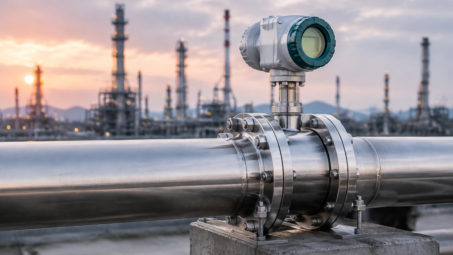
In industrial process control, the accurate measurement of fluid movement is essential for efficiency, safety, and billing. An in-line flow meter is a device installed directly into a piping system, where the fluid passes through the sensor body. Unlike non-invasive methods, in-line meters provide a direct interface with the medium, often resulting in higher precision and faster response times. These instruments are fundamental in sectors ranging from water treatment and chemical processing to oil and gas and food production.
Selecting the correct in-line flow meter requires a deep understanding of the underlying physics of the fluid, the mechanical constraints of the piping, and the specific requirements of the application. This guide explores the primary measurement principles, selection criteria, and installation best practices for industrial professionals.
Core Measurement Principles of In-line Flow Meters
Before selecting an instrument, it is vital to understand how different technologies interact with the fluid. In-line flow meters are generally categorized by the physical principle they employ to derive flow velocity or mass.
Electromagnetic Flow Meters (Magmeters)
Electromagnetic flow meters operate based on Faraday’s Law of Electromagnetic Induction. This principle states that a conductor moving through a magnetic field produces an electrical signal proportional to its velocity. In this case, the conductive liquid (such as water, acids, or slurries) acts as the conductor.
As the fluid flows through the magnetic field generated by the meter’s coils, electrodes located on the pipe wall pick up the induced voltage. Because the sensor body is typically a straight-through tube with no moving parts, magmeters offer zero pressure drop and are highly resistant to wear. However, they require the fluid to have a minimum electrical conductivity, usually greater than 5 μS/cm.
Vortex Shedding Flow Meters
Vortex meters utilize the Karman Vortex Street principle. When a fluid meets an obstruction (a "bluff body") in the flow stream, it creates alternating vortices (swirls) downstream. The frequency at which these vortices are shed is directly proportional to the velocity of the fluid.
A sensor, typically a piezoelectric crystal, detects the pressure pulses caused by these vortices. Vortex meters are highly versatile, capable of measuring liquids, gases, and saturated or superheated steam. They are favored for their durability and lack of moving parts, though they require a minimum Reynolds number to function accurately.
Ultrasonic In-line Flow Meters
In-line ultrasonic meters usually employ the transit-time principle. The meter contains pairs of transducers that send and receive ultrasonic pulses through the fluid. One pulse travels with the flow (downstream), and the other travels against it (upstream).
The time difference between these two pulses is proportional to the flow velocity. Unlike clamp-on ultrasonic meters, in-line versions use wetted transducers that are in direct contact with the fluid, eliminating errors caused by pipe wall interference and providing high accuracy even in clean, non-conductive liquids.
Turbine Flow Meters
Turbine meters are mechanical instruments that feature a multi-bladed rotor mounted on bearings within the flow stream. As the fluid passes through the meter, it pushes the blades, causing the rotor to spin. The rotational speed of the turbine is proportional to the velocity of the fluid.
A magnetic pickup or sensor outside the pressure boundary detects the passage of the rotor blades and converts this into a frequency signal. While extremely accurate for clean, low-viscosity fluids, turbine meters are susceptible to wear and can be damaged by debris or sudden surges in flow.
Selection Criteria for Industrial Applications
Choosing an in-line flow meter involves balancing performance requirements with the physical properties of the process. For comprehensive information on how these flow solutions integrate with broader industrial monitoring systems, engineers can consult the Main Page of our technical resource center.
Key evaluation factors include:
1. Fluid Properties: Is the medium a liquid, gas, or steam? Is it conductive, corrosive, or abrasive? For example, a magmeter is ideal for corrosive acids but useless for deionized water or hydrocarbons.
2. Process Conditions: What are the maximum and minimum operating temperatures and pressures? Vortex meters are often the first choice for high-temperature steam (up to 350°C), whereas plastic-bodied ultrasonic meters might be limited to lower temperatures.
3. Accuracy and Repeatability: Does the application require fiscal-grade billing accuracy (±0.25% or better) or simple process monitoring (±1% to ±2%)?
4. Turndown Ratio: This is the range over which the meter can measure accurately. If your flow fluctuates significantly, you need a meter with a high turndown ratio (e.g., 100:1 for some ultrasonic meters vs. 10:1 for turbine meters).
Technical Comparison of In-line Flow Technologies
The following table summarizes the typical performance characteristics of common in-line flow meter types used in industrial automation.
| Technology | Suitable Fluids | Typical Accuracy | Max Temp (Approx) | Pressure Drop | Moving Parts |
| :— | :— | :— | :— | :— | :— |
| Electromagnetic | Conductive Liquids | ±0.5% of rate | 180°C | Negligible | No |
| Vortex | Liquid, Gas, Steam | ±1.0% (Liquid) | 350°C | Low to Medium | No |
| Ultrasonic | Clean/Dirty Liquids | ±0.5% of rate | 200°C | Negligible | No |
| Turbine | Clean Liquids/Gases | ±0.25% of rate | 150°C | High | Yes |
| Thermal Mass | Clean Gases | ±1.0% of FS | 200°C | Low | No |
Engineering and Installation Guidelines
Even the most advanced in-line flow meter will fail to provide accurate data if installed incorrectly. Proper installation ensures a developed flow profile and protects the sensor from damage.
Straight Pipe Requirements
Most in-line meters require a specific length of straight pipe before (upstream) and after (downstream) the sensor to eliminate turbulence caused by valves, elbows, or pumps. A common rule of thumb is "10D and 5D"—meaning ten times the nominal pipe diameter of straight pipe upstream and five times downstream. If space is limited, flow conditioners or specific meter types (like certain magmeters) may reduce these requirements.
Orientation and Fluid State
For liquid applications, the pipe must always be completely full. Air pockets or partially filled pipes will cause significant measurement errors. In-line meters are ideally installed in vertical pipes with an upward flow direction, as this naturally ensures the pipe remains full and prevents the accumulation of sediment.
Grounding and Electrical Noise
Electromagnetic flow meters are particularly sensitive to electrical noise. Proper grounding to the process fluid is essential. This is typically achieved using grounding rings or electrodes to ensure the meter and the fluid are at the same electrical potential, preventing stray currents from interfering with the low-voltage flow signal.
Operational Limitations and Common Risks
Understanding the limitations of an in-line flow meter prevents premature failure and data inaccuracies.
* Cavitation: If the pressure drops too low within the meter (especially in turbine or vortex types), vapor bubbles can form and collapse. This phenomenon, known as cavitation, can erode internal components and cause massive measurement errors.
* Viscosity Sensitivity: Mechanical meters like turbines are highly sensitive to changes in fluid viscosity. As a liquid thickens, the drag on the rotor increases, leading to under-registration of flow.
* Scale and Buildup: In applications involving hard water or chemical precipitates, scale can build up on the electrodes of a magmeter or the bluff body of a vortex meter. This changes the internal diameter of the pipe or dampens the sensor signal, requiring periodic cleaning or recalibration.
* Vibration: Vortex meters are sensitive to pipe vibration, which the sensor may misinterpret as flow pulses. In high-vibration environments, specialized dual-sensor vortex meters or ultrasonic alternatives should be considered.
Frequently Asked Questions (FAQs)
Q: Can an in-line flow meter measure bidirectional flow?
A: Yes, many electromagnetic and ultrasonic in-line meters are designed to measure flow in both directions, providing separate totals for forward and reverse flow. Turbine and vortex meters are generally unidirectional.
Q: What is the difference between an in-line meter and a insertion meter?
A: An in-line meter consists of a full flow body that replaces a section of the pipe. An insertion meter involves a small probe inserted through a hole in the pipe wall. In-line meters are generally more accurate because they sample the entire flow stream, whereas insertion meters measure a single point.
Q: How often should an in-line flow meter be calibrated?
A: Calibration frequency depends on the industry and the criticality of the measurement. For water treatment, every 2-3 years may suffice. For high-value chemical dosing or custody transfer, annual or semi-annual calibration is standard.
Q: Does pipe material affect in-line meter performance?
A: For magmeters, if the pipe is non-conductive (like PVC), grounding rings are mandatory. For ultrasonic meters, the in-line body is typically metal, so the existing pipe material is less of a factor than it would be for clamp-on sensors.
Conclusion
The implementation of an in-line flow meter is a critical decision in process engineering. By matching the measurement principle—whether electromagnetic, vortex, ultrasonic, or turbine—to the specific characteristics of the fluid and the installation environment, operators can ensure long-term reliability and accuracy. While manufacturers like Welk focus heavily on level measurement instruments, the integration of flow and level data remains the cornerstone of effective industrial automation and inventory management. Following strict installation guidelines and acknowledging the physical limitations of each technology will minimize maintenance costs and maximize the lifespan of the instrumentation.