Flowline Valves
Flowline Valves
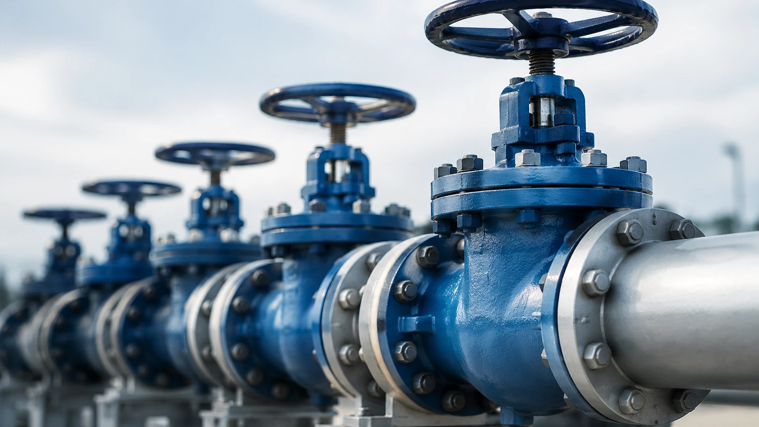
In industrial process engineering, flowline valves serve as the primary mechanical interface for controlling the movement, pressure, and direction of fluids within a piping system. Whether in oil and gas production, chemical processing, or water treatment, these components are essential for maintaining system integrity and operational safety. However, the effectiveness of flowline valves is often dependent on the accuracy of the instrumentation that monitors the vessels they feed or drain.
Integrating high-quality valves with precise level measurement instruments ensures that automation systems can respond to real-time changes in fluid volume. For engineers and procurement specialists, understanding the synergy between flow control and level monitoring is critical for optimizing plant performance. To explore comprehensive measurement solutions, you may visit the Main Page for technical specifications on compatible sensors.
Principles of Level Measurement in Flowline Systems
Before selecting flowline valves, it is necessary to understand the measurement principles used to monitor the media they control. Level measurement provides the feedback loop required for valve actuation, preventing tank overfills or pump cavitation.
Radar Level Measurement (ToF)
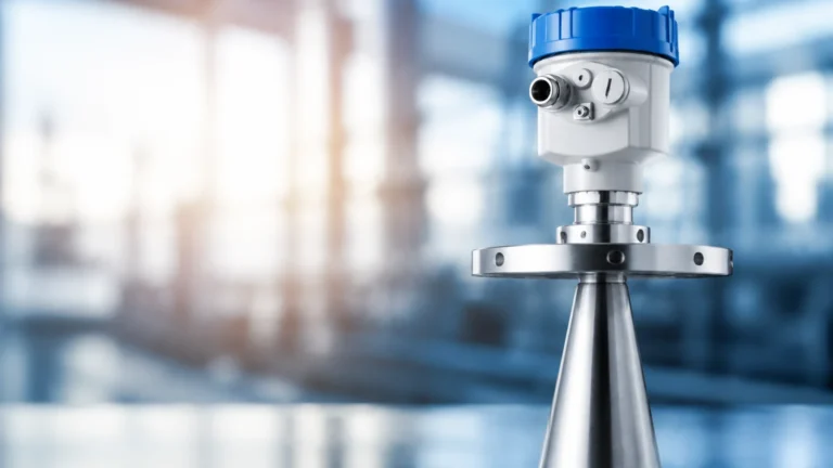
Radar level meters operate on the Time-of-Flight (ToF) principle. The device emits high-frequency microwave pulses (typically in the 26 GHz or 80 GHz range) that travel to the surface of the medium and reflect back to the sensor. The distance is calculated based on the time interval between emission and reception.
In flowline applications involving volatile chemicals or high-pressure hydrocarbons, non-contact radar is preferred because it is unaffected by changes in density, temperature, or pressure. It provides a high degree of accuracy (often ±2 mm) which is vital for modulating control valves in precision dosing applications.
Ultrasonic Level Sensing
Ultrasonic sensors utilize sound waves to determine the distance to the liquid surface. Like radar, they use the ToF principle but rely on the speed of sound. While cost-effective for water treatment and open-channel flowlines, ultrasonic waves are sensitive to air temperature gradients and surface foam. These sensors are best suited for atmospheric tanks where the flowline valves manage non-volatile liquids.
Hydrostatic Pressure Measurement
Hydrostatic level transmitters measure the pressure exerted by a liquid column at a specific depth. The relationship is defined by the formula $P = \rho gh$, where $P$ is pressure, $\rho$ is the density of the liquid, $g$ is gravity, and $h$ is the height of the liquid. In flowlines where the fluid density remains constant, hydrostatic sensors offer a rugged and reliable solution for controlling drain valves in deep sumps or vented tanks.
Magnetic Level Gauges
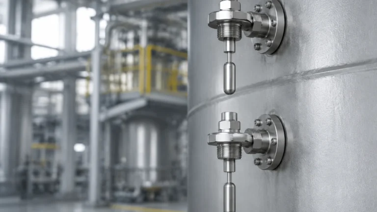
Magnetic level gauges provide a visual indication of the level through a bypass chamber mounted to the side of a vessel. A float containing a permanent magnet moves with the liquid level, actuating mechanical flags or a transmitter. This technology is often paired with flowline valves in high-pressure steam or hazardous chemical service, providing a fail-safe mechanical backup to electronic systems.
Types of Flowline Valves and Their Applications
Flowline valves are categorized by their mechanical action and their specific role in the process loop. Selecting the correct valve type is essential for ensuring that the flow characteristics match the requirements of the level control system.
| Valve Type | Primary Function | Common Flowline Application |
| :— | :— | :— |
| Gate Valve | Isolation | Main flowline shut-off; used when a straight-line flow with minimum restriction is required. |
| Ball Valve | Quick Shut-off | High-pressure flowlines requiring a bubble-tight seal and 90-degree actuation. |
| Globe Valve | Throttling | Used in conjunction with level sensors for precise flow regulation and modulating control. |
| Check Valve | Backflow Prevention | Prevents reverse flow in pump discharge lines to protect level-sensitive equipment. |
| Butterfly Valve | Flow Control | Used in large-diameter flowlines for low-pressure applications like water distribution. |
Isolation Valves
In most flowline configurations, gate and ball valves are used for isolation. When a level sensor detects a high-level alarm, these valves are typically the first line of defense, closing completely to stop the inflow. Gate valves are generally used for on/off service where the valve remains fully open or closed for long periods, while ball valves provide faster actuation for emergency shutdowns.
Regulating Valves
Globe valves are the standard for throttling applications. When a radar or ultrasonic sensor provides a continuous 4-20mA signal to a PLC, the globe valve adjusts its position to maintain a setpoint level. The design of the globe valve allows for fine-tuned control of flow rates, making it indispensable in flowlines that require constant level stabilization.
Selection Criteria for Flowline Components
When specifying flowline valves and level instruments, engineers must evaluate several technical factors to ensure long-term reliability.
1. Media Compatibility: The chemical properties of the fluid dictate the materials for both the valve body and the sensor probe. For corrosive media, stainless steel (316L), Hastelloy, or PTFE-lined components are standard.
2. Pressure and Temperature Ratings: Flowline valves must meet specific ANSI or API pressure classes (e.g., Class 150, 300, or 600). Similarly, level sensors must be rated for the process temperature to prevent electronics failure or seal degradation.
3. Flow Velocity: High-velocity flowlines can cause erosion in valves and turbulence in tanks. If a level sensor is placed near a high-velocity inlet, it may provide erratic readings. Stilling wells or bypass chambers are often required to isolate the sensor from flowline turbulence.
4. Actuation Requirements: Automated flowlines require valves equipped with pneumatic, hydraulic, or electric actuators. The speed of the actuator must be synchronized with the response time of the level sensor to prevent "hunting" or system oscillations.
Installation Considerations and Best Practices
Proper installation is the most significant factor in the performance of a flowline system. Poorly placed valves or sensors can lead to measurement errors and mechanical wear.
Positioning the Level Sensor
Level sensors should never be installed directly above the flowline inlet. The turbulence and splashing caused by the incoming fluid can interfere with radar and ultrasonic signals, leading to false high-level readings. For hydrostatic sensors, placement should be away from high-velocity zones where the "venturi effect" might lower the local pressure and result in inaccurate level data.
Valve Orientation
While many flowline valves can be installed in any orientation, check valves and certain types of globe valves are gravity-dependent. Horizontal installation is generally preferred to prevent the accumulation of sediment in the valve bonnet, which can impede the movement of the stem and affect the level control loop.
Piping Runs
To ensure stable flow and accurate measurement, it is recommended to have at least 5 to 10 pipe diameters of straight run before and after a control valve. This minimizes turbulence, which can cause cavitation in the valve and signal noise in flow-mounted sensors.
Limitations and Operational Risks
Despite advancements in technology, flowline systems face inherent risks that must be managed through design and maintenance.
* Cavitation: In flowline valves where there is a high pressure drop, vapor bubbles can form and collapse, causing physical damage to the valve trim and vibration that can disrupt level sensor electronics.
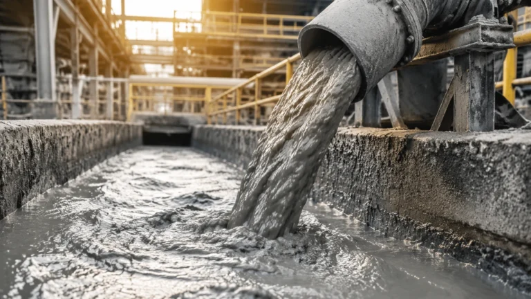
* Scaling and Build-up: In wastewater or mineral-processing flowlines, material build-up on the valve seat or the sensor face can lead to failure. Non-contact radar is often the best solution here, as it does not require physical contact with the media.
* Signal Interference: In metal tanks with internal structures like agitators or baffles, radar signals can produce "false echoes." Modern level meters utilize software-based false echo suppression to ignore these obstructions, but careful placement remains the best practice.
Frequently Asked Questions (FAQ)
Q: Can flowline valves be used to measure flow rate?
No, valves are used to control flow. However, the position of a calibrated control valve, combined with the pressure drop across it, can be used to estimate flow. For accurate measurement, a dedicated flow meter or a level-based volume calculation in a calibrated tank is required.
Q: How often should level sensors in automated flowlines be calibrated?
Calibration frequency depends on the criticality of the process and the media. For most industrial applications, an annual calibration check is sufficient. However, in corrosive or high-scaling environments, quarterly inspections of both the valve seats and sensor probes are recommended.
Q: What is the advantage of using a bypass chamber for level measurement?
A bypass chamber (or side-pipe) isolates the level sensor from the turbulence of the main flowline. This allows for stable measurement even when the tank is being filled or emptied at high velocities. It also allows for maintenance of the sensor without shutting down the main process, provided that isolation valves are installed on the bypass legs.
Q: Are radar level meters compatible with all flowline fluids?
Radar meters require a minimum dielectric constant to reflect the signal. While most industrial liquids are compatible, extremely low-dielectric fluids (like certain liquified gases) may require guided wave radar or high-sensitivity 80 GHz units to ensure a reliable signal.
For more detailed technical guidance on choosing the right instrumentation for your flowline valves and overall process control, please refer to our Main Page for a full catalog of industrial level measurement solutions.