Ifm Guided Wave Radar
Ifm Guided Wave Radar
In the landscape of industrial automation, precise level measurement is a cornerstone of process efficiency and safety. Among the various technologies available, Guided Wave Radar (GWR) has emerged as a highly reliable solution for challenging environments. Specifically, the ifm guided wave radar series, often recognized by the LR designation, provides a robust method for monitoring liquids and bulk solids. This article explores the technical principles, selection criteria, and installation requirements for these sensors, providing an engineering reference for those integrating these devices into industrial systems.
The Fundamentals of Guided Wave Radar Technology
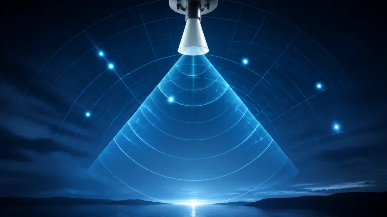
Guided Wave Radar is based on the principle of Time Domain Reflectometry (TDR). Unlike non-contact radar, which broadcasts electromagnetic waves through the air, GWR utilizes a physical probe to guide high-frequency, low-energy electromagnetic pulses from the sensor head to the media being measured.
The Measurement Principle
When the pulse traveling down the probe reaches the surface of the medium, a portion of the pulse energy is reflected back toward the sensor. This reflection occurs due to the change in the dielectric constant ($ε_r$) between the upper medium (usually air or gas, with $ε_r ≈ 1$) and the lower medium (the liquid or solid being measured).
The sensor electronics measure the time of flight—the interval between the emission of the pulse and the reception of the reflected signal. Since the speed of light is constant, the distance to the surface can be calculated with high precision. Because the pulse is physically guided by the probe, the signal remains concentrated, resulting in less signal attenuation compared to through-air radar and making the measurement largely independent of the tank's internal geometry or the presence of steam, dust, or pressure fluctuations.
Key Features and Benefits of ifm Guided Wave Radar Sensors
Ifm guided wave radar systems are designed for versatility in process industries. They are frequently utilized in applications ranging from hydraulic oil monitoring to industrial cleaning agents and water treatment.
1. Modular Probe Concept: Many models allow for the probe to be shortened or replaced in the field. This flexibility is essential for adapting to various tank heights without requiring custom-manufactured units for every application.
2. Digital Communication (IO-Link): A defining feature of modern ifm sensors is the integration of IO-Link. This interface allows for remote parameter setting, detailed diagnostic data (such as signal quality), and digital transmission of the level value, which eliminates the digital-to-analog conversion errors associated with traditional 4-20 mA loops.
3. High Resistance to Surface Turbulence: Because the signal is guided, surface foam or turbulence has a significantly lower impact on measurement stability compared to ultrasonic or non-contact radar technologies.
4. No Moving Parts: As a solid-state electronic device, the GWR sensor requires significantly less maintenance than mechanical float switches or displacers.
Selection Criteria: Choosing the Right Probe Configuration
Selecting the correct probe type is critical for the performance of an ifm guided wave radar. The choice depends on the dielectric constant of the medium, the tank size, and the presence of obstructions.
Probe Types Comparison
| Probe Type | Best Suited For | Maximum Range (Typical) | Dielectric Constant ($ε_r$) Requirement |
| :— | :— | :— | :— |
| Single Rod | Viscous liquids, coating media, and oils | Up to 2m – 4m | $ε_r > 6$ (Lower with coaxial pipe) |
| Coaxial Pipe | Low dielectric fluids (oils), small tanks, plastic tanks | Up to 2m | $ε_r > 1.8$ |
| Rope Probe | Tall silos, bulk solids, large liquid tanks | Up to 75m | $ε_r > 6$ |
Dielectric Constant Considerations
The dielectric constant is the most important factor in GWR selection. Water has a high dielectric constant ($ε_r ≈ 80$), providing a very strong reflection. Hydrocarbons and oils have low dielectric constants ($ε_r ≈ 2$ to $5$), which reflect less energy. For fluids with a low $ε_r$, a coaxial probe is often recommended. The coaxial tube acts as an outer shield, concentrating the electromagnetic field within a narrow space and maximizing the reflected signal strength.
For further technical comparisons and to see how these sensors fit into a broader instrument strategy, engineers can consult the Main Page for detailed product specifications and alternative measurement technologies.
Installation Requirements and Best Practices
To ensure the accuracy of an ifm guided wave radar, several mechanical and electrical installation guidelines must be followed. Failure to adhere to these can result in "ghost signals" or loss of signal.
Mounting Position
* Distance from Walls: The probe should not be mounted too close to the tank wall or internal structures like ladders or pipes. For a single rod probe, a minimum distance of 50 mm (approx. 2 inches) from the wall is typically required to prevent interference reflections.
* Inflow Stream: Never install the sensor directly in the path of the filling stream. The force of the incoming liquid can damage the probe, and the turbulence will cause erratic readings.
* Dead Zones: Every GWR sensor has an upper and lower "dead zone" (also known as the blocking distance). Measurement is not possible within these regions. The upper dead zone is usually near the process connection (mounting flange), while the lower dead zone is at the very tip of the probe.
Tank Material and Grounding
For single rod probes, the metal tank top acts as a launch plate for the radar pulse. If the sensor is installed on a plastic tank, a metal launch plate or a coaxial probe must be used to provide the necessary reference ground for the electromagnetic pulse to propagate correctly.

Limitations and Application Constraints
While highly versatile, ifm guided wave radar is not a universal solution for every level measurement challenge. Engineers should be aware of the following limitations:
* Heavy Build-up: While GWR can handle some coating, extremely viscous or conductive media that bridge the gap between the probe and the tank wall (or the inner rod and the coaxial tube) will cause false high-level readings.
* Bridging in Solids: In bulk solids applications, the lateral forces exerted on a rope probe can be immense. If the material bridges or collapses, it can pull the probe out of its mounting.
* Extremely Low Dielectrics: Media with a dielectric constant below 1.8 may not reflect enough energy for a reliable measurement, even with a coaxial probe.
* Probe Length Constraints: In very tall tanks where a rod probe is used, mechanical stability becomes an issue. For depths exceeding 4 meters (approx. 13 feet), rope probes are generally preferred, though they require a weight at the end to keep them taut.
Comparison with Alternative Level Measurement Technologies
Understanding where ifm guided wave radar sits relative to other technologies helps in making an informed procurement decision.
* GWR vs. Ultrasonic: Ultrasonic sensors are non-contact and cost-effective but are sensitive to air temperature, heavy steam, and vacuum conditions—factors that do not affect GWR.
* GWR vs. Non-Contact Radar: Non-contact radar is ideal for corrosive media because the sensor does not touch the liquid. However, GWR is often better for low-dielectric liquids and tanks with complex internal geometries where through-air signals would be scattered.
* GWR vs. Hydrostatic Pressure: Hydrostatic sensors measure the weight of the liquid column. They are excellent for constant-density liquids but fail if the density changes. GWR is a volume-independent, direct distance measurement.
Frequently Asked Questions (FAQ)
Q: Can I cut the probe of an ifm guided wave radar to a custom length?
A: Yes, most ifm LR-series probes are designed to be cut to length. After cutting, the new probe length must be entered into the sensor's parameters via the display or IO-Link interface to maintain accuracy.
Q: Does the pressure inside the tank affect the measurement?
A: No. Because the measurement relies on electromagnetic pulses, changes in tank pressure or vacuum do not affect the speed of the signal or the accuracy of the level reading.
Q: How does foam affect the ifm guided wave radar?
A: In most cases, the radar pulse will pass through light foam and reflect off the liquid surface. However, very dense, high-dielectric foam may be detected as the surface. Testing is recommended for specific foaming agents.
Q: Is it possible to measure the interface between two liquids?
A: Yes, GWR technology is capable of interface measurement (e.g., the boundary between oil and water). This requires the upper liquid to have a lower dielectric constant than the lower liquid, allowing a portion of the pulse to pass through the top layer and reflect off the second layer.
For comprehensive support in selecting the appropriate level measurement technology for your specific industrial application, please refer to the technical resources available on our Main Page.