Oil Level Transducer
Oil Level Transducer
In industrial automation and process control, the accurate measurement of oil levels is essential for operational efficiency, safety, and inventory management. An oil level transducer is a precision instrument designed to convert the physical height or volume of oil in a tank or vessel into an electrical signal, typically 4-20mA, 0-10V, or a digital protocol like Modbus or HART. Unlike simple switches that only indicate high or low points, a transducer provides continuous monitoring, allowing operators to track consumption rates, detect leaks, and optimize refill schedules.
Selecting the appropriate oil level transducer requires a deep understanding of the fluid’s properties—such as viscosity, dielectric constant, and temperature—as well as the physical constraints of the storage environment. This guide explores the fundamental measurement principles, selection criteria, and installation best practices for engineering professionals.
Understanding the Role of an Oil Level Transducer in Industrial Processes
Oils, ranging from thin hydraulic fluids and lubricants to heavy crude and fuel oils, present unique challenges for level measurement. They are often non-conductive, may have varying viscosities based on temperature, and can produce vapors that interfere with certain sensing technologies.
The primary function of an oil level transducer is to provide real-time data to a Programmable Logic Controller (PLC) or a dedicated display unit. This data is critical in applications such as:
* Hydraulic Power Units: Ensuring sufficient fluid levels to prevent pump cavitation.
* Fuel Storage Tanks: Monitoring inventory for diesel generators or heating systems.
* Transformer Oil Monitoring: Detecting slow leaks in high-voltage equipment to prevent catastrophic failure.
* Lubrication Systems: Maintaining consistent oil supply to large rotating machinery.
For a comprehensive overview of industrial-grade sensing hardware, engineers often consult the Main Page of specialized manufacturers to evaluate the compatibility of different sensor housings and output protocols.
Primary Measurement Principles for Oil Level Detection
Before selecting a specific model, it is vital to understand the physics behind the most common measurement technologies. No single technology is universal; each has strengths depending on the oil type and tank conditions.
Hydrostatic Pressure Sensing
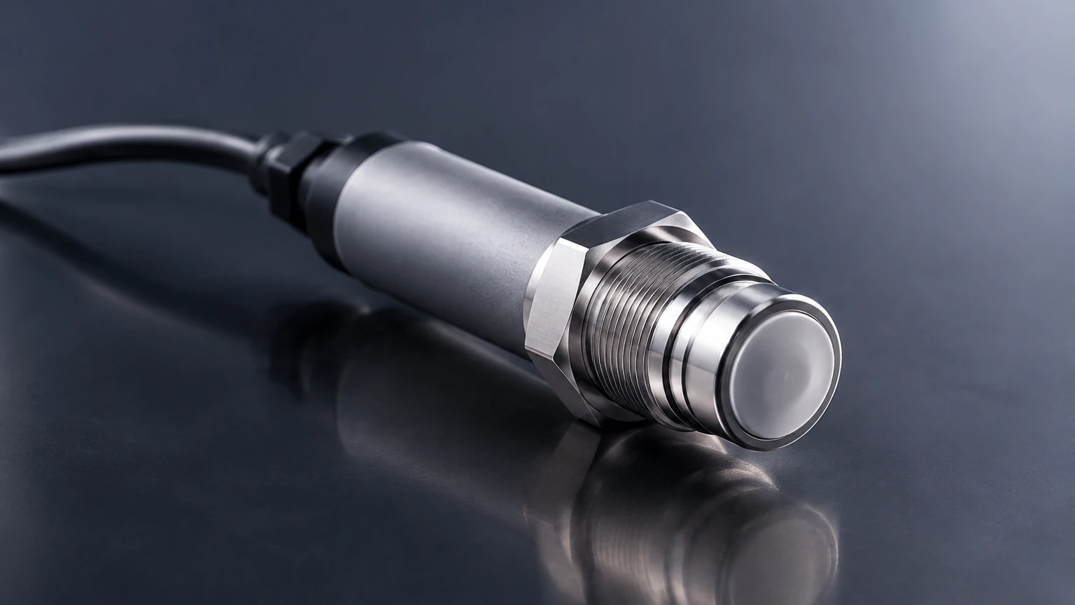
Hydrostatic transducers measure the pressure exerted by the column of liquid above the sensor diaphragm. The relationship is defined by the formula:
P = ρ × g × h
Where *P* is pressure, *ρ* (rho) is the density of the oil, *g* is gravity, and *h* is the height of the liquid.
Because oils are generally lighter than water (with specific gravities often between 0.7 and 0.9), the transducer must be calibrated to the specific density of the fluid. These sensors are typically submersible or externally mounted at the bottom of the tank. They are cost-effective and reliable for vented tanks where the vapor pressure is negligible.
Ultrasonic Level Measurement
Ultrasonic transducers are non-contact devices that emit high-frequency sound pulses. The sensor measures the time it takes for the pulse to travel to the oil surface and return. This "Time-of-Flight" (ToF) is then converted into distance.
While effective for many lubricants, ultrasonic sensors can struggle with heavy oil vapors or high-pressure environments, as the speed of sound changes with gas density and temperature. They are best suited for stable, atmospheric storage tanks containing clean oils.
Radar (Microwave) Technology
Radar transducers work similarly to ultrasonic sensors but use electromagnetic waves instead of sound. There are two main types:
1. Non-contact Radar: Emits a signal through the air. It is highly effective for oils because it is unaffected by vapors, vacuum, or high temperatures. However, because oils have a low dielectric constant (εr), the reflected signal is weaker than it would be for water.
2. Guided Wave Radar (GWR): Uses a physical probe (cable or rod) to guide the microwave signal to the liquid surface. GWR is often preferred for oil level transducer applications because the probe concentrates the energy, ensuring a reliable return signal even from fluids with low dielectric properties.
Magnetic Level Gauging
This technology utilizes a float containing an internal magnet that moves along a guide tube. Inside the tube, a series of reed switches or a magnetostrictive wire detects the position of the float. This is a robust mechanical-electronic hybrid solution that is immune to foam, vapors, and dielectric changes, making it a favorite for high-pressure oil separators and heavy fuel tanks.
Technical Selection Criteria for Oil Applications
When specifying an oil level transducer, engineers must evaluate several variables to ensure long-term reliability and accuracy.
1. Fluid Properties
* Viscosity: High-viscosity oils (like heavy gear oil or crude) can coat sensors. In such cases, non-contact radar or flush-diaphragm hydrostatic sensors are preferred over mechanical floats.
* Dielectric Constant: If using radar, the εr of the oil must be known. Most oils fall between 1.8 and 4.0. Lower values require more sensitive radar units or guided wave technology.
* Specific Gravity: For hydrostatic sensors, the specific gravity must be constant. If the oil type changes or temperature fluctuations significantly alter the density, the level reading will drift.
2. Tank Geometry and Environment
* Internal Obstructions: Agitators, ladders, or heating coils can interfere with ultrasonic or non-contact radar signals. GWR or hydrostatic sensors are often better in crowded tanks.
* Pressure and Temperature: Ensure the transducer materials (SS316, PTFE, FKM) are compatible with the operating temperature and that the sensor is rated for the tank's maximum pressure.
3. Output and Integration
Modern systems often require more than a simple analog signal. Consider whether the application needs:
* 4-20mA with HART: For remote calibration and diagnostics.
* Modbus RTU: For direct integration into digital SCADA networks.
* Local Display: For manual checking by floor operators.
Comparative Analysis of Oil Level Transducer Technologies
| Technology | Contact Type | Accuracy | Best For | Main Limitation |
| :— | :— | :— | :— | :— |
| Hydrostatic | Contact | ±0.25% to 0.5% | Deep tanks, vented vessels | Affected by density changes |
| Ultrasonic | Non-contact | ±0.25% | Clean oils, atmospheric tanks | Sensitive to foam and vapors |
| Guided Wave Radar | Contact | ±2 mm to 5 mm | Low dielectric oils, foam | Material buildup on probe |
| Non-contact Radar | Non-contact | ±1 mm to 3 mm | High temp, corrosive oils | Weak signal on very low εr |
| Magnetic Float | Contact | ±5 mm to 10 mm | High pressure, bypass units | Moving parts can wear/stick |
Installation Guidelines and Best Practices
Correct installation is as important as selecting the right technology. Failure to follow engineering best practices often leads to erratic readings or premature sensor failure.
Mounting Position
For top-mounted sensors (Radar, Ultrasonic), the transducer should be placed away from the tank wall to avoid false reflections (the "ringing" effect). A common rule of thumb is to mount the sensor at least 200 mm from the wall or 1/10th of the tank diameter. Additionally, ensure the sensor is not placed directly over the fill inlet, as the turbulence and splashing during filling will cause signal noise.
The Dead Zone (Blanking Distance)
Every ultrasonic and radar transducer has a "dead zone" directly beneath the sensor face where it cannot measure. If the oil level rises into this zone, the sensor may report an error or a fixed maximum value. Always mount the sensor high enough so that the maximum expected oil level remains below the dead zone.
Stilling Wells and Bypass Chambers
In tanks with significant turbulence, foam, or internal obstructions, a stilling well (a vertical pipe) can be used to provide a calm surface for measurement. This is particularly effective for radar and ultrasonic sensors. Alternatively, a bypass chamber mounted to the side of the tank allows for maintenance without emptying the vessel.
Cable Protection and Venting
For submersible hydrostatic transducers, the cable usually contains a small vent tube to compensate for atmospheric pressure changes. It is critical that this tube is not kinked or blocked by moisture, as this will cause significant measurement errors. Using a specialized junction box with a desiccant filter is recommended.
Limitations and Operational Challenges
While oil level transducers are highly accurate, they are not "set and forget" devices. Several factors can impact performance over time:
1. Temperature Drift: As oil heats up, it expands, and its density decreases. This can cause a hydrostatic sensor to indicate a lower level than actually exists, even though the volume is the same. High-end transducers often include integrated temperature compensation to mitigate this.
2. Paraffin or Wax Buildup: In crude oil or heavy fuel applications, waxes can precipitate out of the oil and coat the sensor probe or diaphragm. This is a common cause of "frozen" readings. Periodic cleaning or the use of PTFE-coated probes may be necessary.
3. Signal Absorption: Some synthetic oils have extremely low dielectric constants that may absorb radar energy rather than reflecting it. In these rare cases, a magnetic level gauge or a hydrostatic sensor is a more reliable alternative.
Frequently Asked Questions (FAQ)
Q: Can I use a water level sensor for oil?
A: It depends on the technology. An ultrasonic or radar sensor will work, though it may need recalibration for the different dielectric constant or speed of sound. A hydrostatic sensor designed for water will provide an incorrect reading for oil unless the specific gravity offset is programmed into the controller.
Q: How do I measure oil level in a pressurized tank?
A: For pressurized tanks, a differential pressure (DP) transducer or a Guided Wave Radar (GWR) is typically used. A standard hydrostatic sensor cannot distinguish between the liquid head pressure and the overhead gas pressure.
Q: What is the best transducer for hydraulic oil with lots of bubbles?
A: Air bubbles (aeration) interfere with ultrasonic and radar signals. A magnetic float level transducer or a hydrostatic pressure sensor is generally more effective in aerated fluids because they are less affected by surface conditions.
Q: Does the color of the oil affect the measurement?
A: No. Whether the oil is clear, amber, or black, it does not affect radar, ultrasonic, or hydrostatic technologies. Only optical sensors (which are rarely used for continuous level) are affected by opacity.
Conclusion
Selecting the right oil level transducer is a balance of technical requirements, environmental constraints, and budget. For most industrial applications, Guided Wave Radar and Hydrostatic sensors offer the best combination of accuracy and reliability. However, the specific nuances of the oil being measured—such as its tendency to foam or its dielectric properties—must guide the final engineering decision.
To explore specific hardware configurations and technical data sheets for various industrial environments, you may review the options available on the Main Page to find a solution tailored to your project’s specific needs.