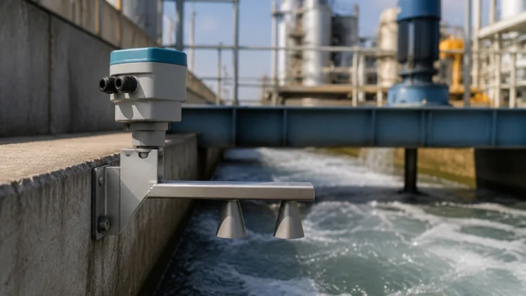
Level Monitoring Systems for Oem
Level Monitoring Systems for Oem
Original Equipment Manufacturers (OEMs) across industries such as water treatment, chemical processing, and power generation require reliable, repeatable, and cost-effective level measurement solutions to integrate into their proprietary machinery. Selecting the right level monitoring systems for OEM applications involves a deep understanding of measurement physics, environmental constraints, and integration requirements. This guide examines the primary technologies used in industrial level measurement and provides an engineering framework for selection and installation.
Core Measurement Principles
Before selecting a level monitoring system, it is essential to understand the physical principles that govern different sensing technologies. Each method has specific strengths and limitations based on the medium being measured and the vessel environment.
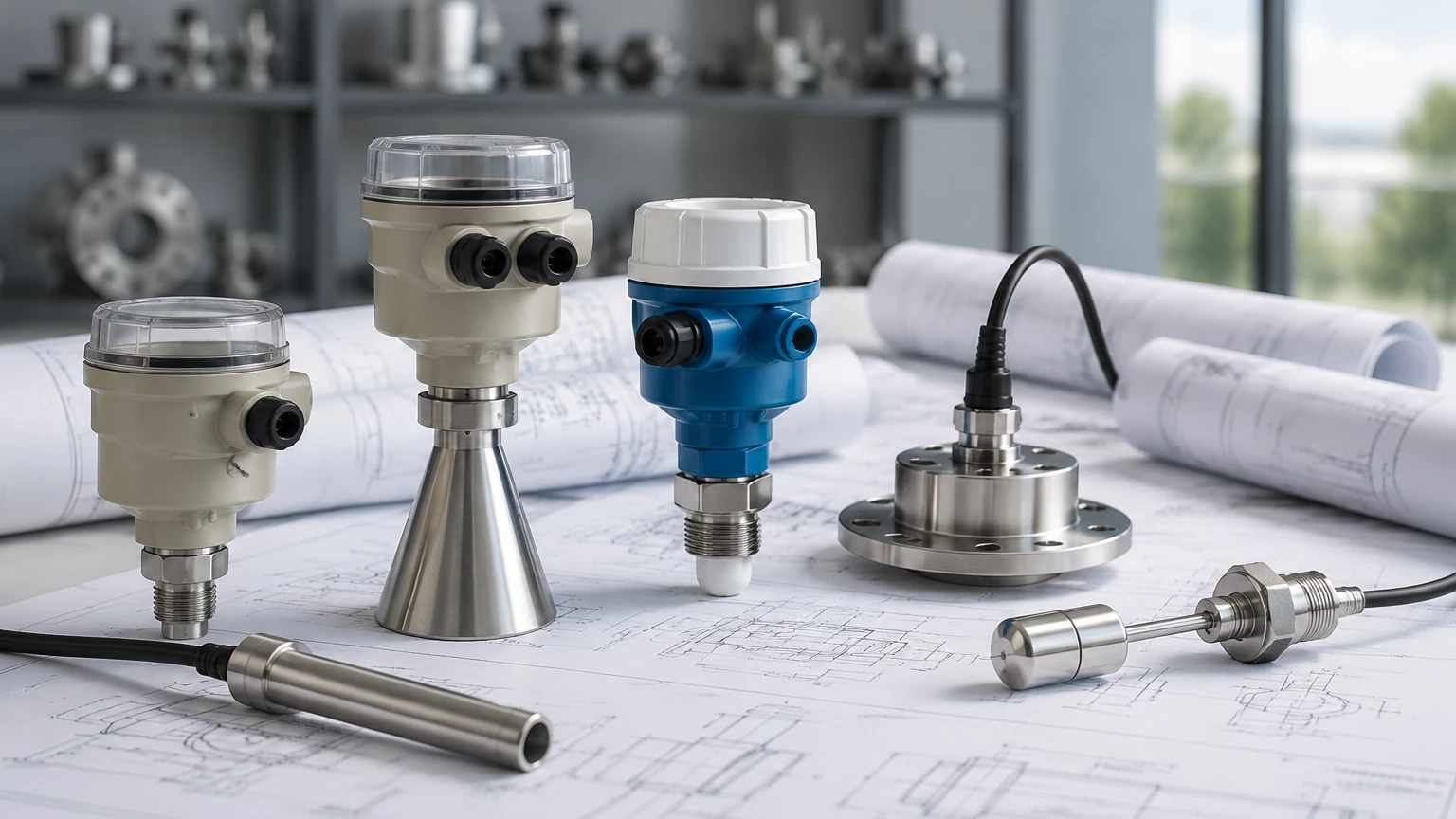
Radar Level Measurement
Radar level meters operate on the Time-of-Flight (ToF) principle. The sensor emits high-frequency microwave pulses (typically in the 26 GHz or 80 GHz range) that travel at the speed of light. When these pulses hit the surface of the medium, they are reflected back to the sensor. The system calculates the distance based on the time interval between transmission and reception.
* Non-contact: Since the sensor does not touch the medium, it is ideal for corrosive or sterile applications.
* Versatility: Radar is largely unaffected by temperature, pressure, or vacuum conditions, making it a premium choice for complex OEM skids.
Ultrasonic Level Sensors
Similar to radar, ultrasonic sensors use ToF but utilize sound waves instead of electromagnetic waves. The transducer emits an ultrasonic pulse that reflects off the liquid or solid surface.
* Cost-Effectiveness: Generally more affordable than radar, making it a popular choice for high-volume level monitoring systems for OEM integration in water and wastewater applications.
* Medium Sensitivity: Sound speed varies with air temperature and density, requiring integrated temperature compensation for accuracy.
Hydrostatic Level Transmitters
Hydrostatic sensors measure the pressure exerted by a liquid column. According to the principle of hydrostatics, the pressure ($P$) at a certain depth is proportional to the height of the liquid ($h$), the density of the liquid ($
ho$), and gravity ($g$): $P =
ho gh$.
* Contact Measurement: These sensors are either submerged in the liquid or mounted to a flange at the bottom of the tank.
* Simplicity: They are highly reliable for vented tanks where the liquid density remains constant.
Magnetic Level Gauges and Switches
Magnetic gauges use a float containing a permanent magnet that moves with the liquid level. This float acts upon an external scale or a series of reed switches (for level switches) to provide visual and electrical feedback.
* Visual Redundancy: Provides a physical indication of level without needing power, which is critical for safety-critical OEM equipment.
Evaluation Criteria for OEM Integration
When designing level monitoring systems for OEM applications, engineers must look beyond basic accuracy. The following criteria are vital for successful integration into larger systems:
1. Communication Protocols: OEMs often require specific outputs to interface with PLCs or IoT gateways. Common standards include 4-20mA, HART, Modbus RTU, and RS485.
2. Form Factor and Mounting: Space is often limited in compact machinery. Sensors with small process connections (e.g., G1/2" or 1" NPT) and low-profile housings are frequently preferred.
3. Material Compatibility: The wetted parts must resist the chemical properties of the medium. Options typically include 316L stainless steel, PTFE, PP, or PVDF.
4. Customization (OEM/ODM): Many manufacturers, such as Welk, offer customized cable lengths, specialized branding, and pre-configured software settings to streamline the OEM assembly process.
Technology Selection Table
The following table provides a comparative overview to assist in the initial selection of level monitoring systems for OEM projects.
| Technology | Accuracy | Typical Range | Temperature Range | Pressure Range | Ideal Media |
| :— | :— | :— | :— | :— | :— |
| 80GHz Radar | ±2 mm | Up to 120 m | -40°C to +200°C | -1 to 40 bar | Liquids, Slurries, Solids |
| Ultrasonic | ±0.25% FS | 0.3 m to 20 m | -40°C to +70°C | Atmospheric | Water, Dilute Chemicals |
| Hydrostatic | ±0.5% FS | 1 m to 200 m | -20°C to +80°C | N/A (Submersible) | Clean Water, Fuel, Oil |
| Magnetic Gauge | ±5 mm | 0.3 m to 6 m | -50°C to +400°C | Up to 160 bar | Acids, Solvents, High-Temp |
Installation Considerations
Correct installation is critical to ensure the longevity and accuracy of level monitoring systems for OEM equipment. Failure to follow these guidelines often results in signal interference or premature sensor failure.
Avoiding Dead Zones
Every non-contact sensor (Radar and Ultrasonic) has a "dead zone" or "blocking distance" directly beneath the sensor face where measurements cannot be taken. For ultrasonic sensors, this is typically 0.2 m to 0.5 m, while high-frequency radar sensors may have a dead zone as small as 0.05 m. OEMs must design tank heights or mounting brackets to account for this gap.
Obstructions and False Echoes
In small OEM tanks, internal components like agitators, heating coils, or ladders can create false reflections.
* Radar/Ultrasonic: Ensure the beam angle does not intersect with these obstructions. Modern sensors allow for "false echo suppression," where the software is taught to ignore static reflections.
* Positioning: Mount the sensor at least 200 mm from the tank wall to avoid side-wall interference.
Turbulence and Foam
Heavy foam can absorb ultrasonic signals, leading to signal loss. In such cases, radar or hydrostatic sensors are preferred. If the liquid surface is highly turbulent due to an inlet pipe, a stilling well or bypass pipe can be used to provide a stable surface for measurement.
Common Risks and Limitations
Engineers must be aware of the specific environmental factors that can compromise level monitoring systems for OEM use:
* Vapor and Condensation: While radar can penetrate most vapors, heavy steam or condensation on an ultrasonic transducer face can attenuate the signal. Sensors with a "dripping" lens design or PTFE face are recommended for high-humidity environments.
* Vacuum Conditions: Ultrasonic sensors cannot function in a vacuum because sound waves require a medium (air) to travel. Radar or hydrostatic sensors must be used instead.
* Electrical Noise: OEM machinery often contains Variable Frequency Drives (VFDs) and motors that generate electromagnetic interference (EMI). Sensors should be shielded and grounded correctly to prevent signal drift.
For a comprehensive look at available hardware and technical specifications, engineers should visit the Main Page to review product options and application support.
Frequently Asked Questions (FAQs)
Q: What is the benefit of 80 GHz radar over 26 GHz for OEM tanks?
A: 80 GHz radar has a much narrower beam angle (often as low as 3°). This allows the sensor to be installed in smaller tanks with more internal obstructions without picking up false echoes from the walls or agitators.
Q: Can hydrostatic sensors be used in pressurized tanks?
A: Standard submersible hydrostatic sensors are designed for vented (atmospheric) tanks. For pressurized tanks, a differential pressure transmitter is required to subtract the top-side gas pressure from the total pressure at the bottom.
Q: How do I handle level measurement in aggressive acids?
A: For aggressive chemicals, non-contact radar with a PTFE-coated antenna or a magnetic level gauge with a plastic-lined chamber are the most reliable options. These materials prevent corrosion and ensure a long service life.
Q: What is the typical lead time for customized OEM level sensors?
A: While standard products may be available immediately, customized level monitoring systems for OEM—including specific cable lengths or custom calibration—typically have a lead time of 2 to 4 weeks depending on the complexity and volume.
Conclusion
Selecting level monitoring systems for OEM applications requires a balance between technical performance and commercial viability. By understanding the underlying physics of radar, ultrasonic, and hydrostatic measurement, engineers can specify solutions that minimize maintenance and maximize accuracy within their equipment. For detailed engineering data and to explore specialized instrumentation, refer to the Main Page for further guidance on industrial level measurement.