Liquid Level Transducer
Liquid Level Transducer
In the landscape of industrial automation, the liquid level transducer serves as a fundamental sensing component. Unlike a simple level switch that provides binary (on/off) data, a transducer provides continuous measurement, converting the physical height of a liquid into a standardized electrical signal—typically 4-20mA, 0-10V, or digital protocols like RS485 Modbus. For process engineers and facility managers, selecting the correct liquid level transducer is critical for maintaining operational safety, optimizing inventory management, and ensuring the precision of chemical dosing or water treatment processes.
This guide examines the primary measurement principles utilized by modern transducers, provides a framework for selection, and outlines the practical installation considerations necessary for long-term reliability.
Core Measurement Principles
Before selecting a liquid level transducer, it is essential to understand the physics behind the measurement. Industrial transducers generally fall into two categories: contact and non-contact.
1. Hydrostatic Pressure (Contact)
Hydrostatic transducers measure the pressure exerted by a liquid column. According to the principle of hydrostatics, the pressure at the bottom of a tank is directly proportional to the height of the liquid above it, multiplied by the liquid's density and the force of gravity ($P = \rho gh$).
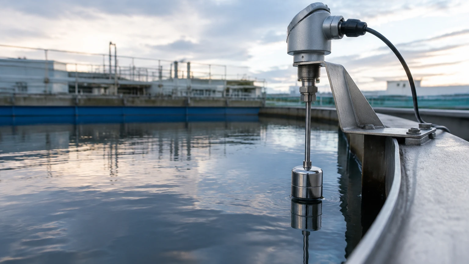
* Submersible Transducers: These are lowered directly into the liquid. They feature a vented cable to compensate for atmospheric pressure changes.
* External Pressure Transmitters: Mounted at the bottom or side of a tank via a flange or threaded connection.
2. Ultrasonic (Non-Contact)
Ultrasonic transducers emit high-frequency sound waves that travel through the air, bounce off the liquid surface, and return to the sensor. The device calculates the distance based on the time-of-flight. Because they do not touch the media, they are ideal for corrosive or dirty liquids. However, they are sensitive to air temperature fluctuations and heavy foam.
3. Radar (Non-Contact or Guided)
Radar technology uses electromagnetic waves (microwaves).
* Non-Contact Radar: Emits waves (often at 26GHz or 80GHz) that reflect off the liquid surface. It is highly accurate and unaffected by vacuum, pressure, or temperature changes in the vapor space.
* Guided Wave Radar (GWR): Uses a probe or cable to guide the microwave signal. This is particularly effective for low dielectric liquids or tanks with complex internal geometries.
4. Magnetic Level Gauges and Transducers
Magnetic systems use a float containing a magnet that moves along a bypass chamber or a guide tube. A series of reed switches or a magnetostrictive element inside the tube detects the float's position and converts it into a continuous output signal.
Selection Criteria for Liquid Level Transducers
Choosing a liquid level transducer requires a detailed analysis of the application environment. Engineers should evaluate the following five factors:
Media Characteristics
The chemical compatibility of the transducer’s wetted parts is paramount. For example, a 316L stainless steel housing may suffice for water, but PTFE or PVDF coatings are required for concentrated acids. Additionally, the dielectric constant of the liquid affects radar performance, while density affects hydrostatic measurements.
Tank Geometry and Obstructions
Internal structures like agitators, ladders, or heating coils can interfere with ultrasonic and radar signals. In such cases, guided wave radar or hydrostatic sensors may be more appropriate. The "dead zone" (or blocking distance) at the top of the sensor must also be considered to prevent measurement loss when the tank is full.
Environmental Conditions
If the tank is pressurized or under vacuum, ultrasonic sensors will fail because sound requires a medium (air) to travel. Radar is the preferred choice for high-pressure or high-temperature reactors. For outdoor applications, surge protection and IP68 ingress protection are standard requirements.
Output and Integration
Most industrial systems rely on the 4-20mA loop for its noise immunity over long distances. However, for complex setups, digital outputs like HART or Modbus allow for remote diagnostics and multi-variable data transmission (e.g., level and temperature).
Technical Comparison Table
| Technology | Accuracy | Best For | Main Limitation |
| :— | :— | :— | :— |
| Hydrostatic | ±0.1% to 0.5% | Deep wells, open tanks, vented vessels | Affected by changes in liquid density |
| Ultrasonic | ±0.25% of range | Water treatment, chemical storage | Sensitive to foam, vapor, and vacuum |
| Radar (80GHz) | ±1mm to 2mm | Precision process tanks, agitated liquids | Higher initial cost compared to ultrasonic |
| Magnetic | ±5mm to 10mm | High-pressure boilers, oil/gas bypass | Mechanical float can get stuck in viscous fluids |
Installation Best Practices
Proper installation is the most significant factor in transducer longevity. Even the most advanced liquid level transducer will provide erratic data if incorrectly positioned.
1. Avoid the Fill Stream: Never install a transducer directly under the inlet pipe. The turbulence and falling liquid will create false echoes or erratic pressure spikes.
2. Mounting Position: For ultrasonic and radar sensors, the transducer should be mounted at least 200mm to 500mm away from the tank wall to prevent side-wall reflections. In domed-roof tanks, avoid mounting the sensor in the exact center, as the dome can act as a parabolic reflector, intensifying noise.
3. Stilling Wells: In applications with heavy surface agitation or foam, installing the transducer inside a stilling well (a vertical pipe) can provide a calm surface for more accurate measurement.
4. Submersible Cable Care: When installing hydrostatic submersible transducers, ensure the vented cable is not kinked. The vent tube must terminate in a dry environment (often using a desiccant bellows) to prevent moisture from entering the transducer internals.
Common Risks and Limitations
While modern transducers are robust, certain process conditions present ongoing risks:
* Foam Accumulation: Heavy, dense foam can absorb ultrasonic and radar signals. If foam is a permanent process feature, hydrostatic or guided wave radar sensors are usually the only reliable options.
* Build-up and Coating: Viscous liquids or those that crystallize can coat the sensor face. While some radar sensors can "see through" thin coatings, significant build-up on an ultrasonic transducer will eventually lead to signal loss.
* Temperature Gradients: Rapid temperature changes in the air space above a liquid can change the speed of sound, causing ultrasonic sensors to drift. Integrated temperature compensation helps, but it cannot always account for stratified air layers.
Frequently Asked Questions (FAQ)
Q: How often should a liquid level transducer be calibrated?
A: For most industrial applications, an annual calibration check is recommended. However, in regulated industries like pharmaceutical or food production, semi-annual calibration may be required. Hydrostatic sensors may require more frequent zero-point checks if the liquid density varies.
Q: Can one transducer measure multiple types of liquids?
A: Non-contact radar and ultrasonic sensors can measure different liquids without reconfiguration, provided the dielectric constant (for radar) is above the minimum threshold. Hydrostatic sensors must be recalibrated if the liquid density changes, as the pressure-to-level calculation depends on a constant density.
Q: What is the difference between a level transmitter and a level transducer?
A: In common industrial parlance, the terms are often used interchangeably. Technically, a transducer converts one form of energy (pressure, sound) into an electrical signal, while a transmitter conditions that signal for long-distance transmission (e.g., 4-20mA). Most modern industrial "transducers" are technically transmitters.
Conclusion
The selection of a liquid level transducer is a balance between technical requirements and budget constraints. While ultrasonic sensors offer a cost-effective non-contact solution for water and wastewater, the precision and versatility of 80GHz radar are increasingly becoming the standard for complex chemical and industrial processes. For deep-well or simple vented tank applications, the hydrostatic transducer remains a reliable, time-tested choice.
For engineers seeking specific hardware specifications or customized OEM solutions, it is advisable to consult with a professional manufacturer to ensure the instrument's wetted materials and signal processing capabilities match the intended application. You can Review product options and application support to find the specific configurations required for your project, including radar, ultrasonic, and hydrostatic variants designed for global industrial standards.