Liquid Level Monitoring
Liquid Level Monitoring
In industrial process control, liquid level monitoring is the foundational process of measuring the height, volume, or position of a fluid within a tank, silo, or open channel. Accurate level data is critical for inventory management, process safety, and operational efficiency. Whether managing volatile chemicals in a refinery or monitoring water levels in a municipal treatment plant, selecting the correct instrumentation requires a deep understanding of physics, fluid dynamics, and environmental constraints.
For engineers and facility managers, the goal of a monitoring system is to provide a reliable data stream that prevents overfills, ensures pump protection, and maintains precise batching ratios. This guide examines the core technologies used in modern liquid level monitoring, provides selection frameworks, and addresses common installation challenges.
Core Measurement Principles
Before selecting a device from a Main Page of industrial instrumentation, it is essential to understand how different sensors interact with the process media. Level measurement is generally categorized into two types: continuous measurement and point level detection.
1. Radar Level Measurement (Time of Flight)
Radar level transmitters utilize electromagnetic waves, typically in the microwave spectrum, to determine the distance to the liquid surface. There are two primary methods: Guided Wave Radar (GWR) and Non-Contact (Free-Space) Radar.
* Non-Contact Radar: These devices emit a signal (often at 26 GHz or 80 GHz) that reflects off the liquid surface and returns to the sensor. The time taken for the signal to travel is proportional to the distance. Higher frequency radars (80 GHz) offer narrower beam angles, making them ideal for tanks with internal obstructions like agitators or heating coils.
* Guided Wave Radar: This method uses a probe (cable or rod) to guide the microwave pulse directly to the liquid surface. It is particularly effective for liquids with low dielectric constants or in applications where heavy foam or steam would scatter a free-space signal.
2. Ultrasonic Level Sensors
Ultrasonic sensors function similarly to radar but use sound waves instead of electromagnetic pulses. The transducer emits an ultrasonic pulse that travels through the air, hits the liquid surface, and bounces back.
Because sound speed is affected by air temperature, most industrial ultrasonic sensors include an integrated temperature sensor to compensate for these changes. These are widely used in water and wastewater applications due to their cost-effectiveness and non-contact nature, though they are limited in high-pressure or vacuum environments where sound cannot travel effectively.
3. Hydrostatic Pressure Measurement
Hydrostatic monitoring relies on the principle that the pressure at the bottom of a vessel is directly proportional to the height of the liquid column above it ($P = \rho gh$).
* Submersible Transmitters: These are lowered into the liquid and measure the pressure exerted by the fluid.
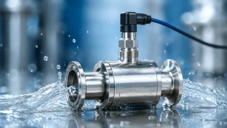
* External Pressure Transducers: Mounted to a flange or threaded connection at the bottom of the tank, these measure the pressure through the vessel wall.
This method is highly reliable for vented tanks but requires compensation (differential pressure) if the tank is pressurized, as the overhead gas pressure would otherwise skew the reading.
4. Magnetic Level Gauges
Magnetic level monitoring involves a float containing an internal magnet that moves with the liquid level inside a bypass chamber. Outside the chamber, a series of magnetic flags or a transmitter responds to the float's position. This provides both a visual indication for local operators and an electronic signal for the control room. It is a preferred method for high-pressure, high-temperature, or toxic fluids where a direct sight glass would be a safety risk.
Technical Selection Criteria
Choosing the right technology for liquid level monitoring depends on a matrix of variables. No single sensor is universal. Engineers must evaluate the following factors:
1. Media Characteristics: Is the liquid corrosive, viscous, or prone to coating? Radar is often better for corrosive media, while hydrostatic sensors must be made of compatible alloys (e.g., Hastelloy or Titanium).
2. Process Conditions: What are the maximum and minimum temperatures and pressures? Ultrasonic sensors typically fail above 80°C (176°F), whereas radar can handle temperatures exceeding 400°C (752°F).
3. Vessel Geometry: Is the tank tall and narrow, or short and wide? Are there internal baffles or agitators? Narrow beam radar is suited for complex geometries.
4. Accuracy Requirements: Does the process require millimeter-level precision for custody transfer, or is a ±1% error margin acceptable for general inventory?
Technology Comparison Table
| Technology | Measurement Type | Accuracy | Max Range | Ideal Applications |
| :— | :— | :— | :— | :— |
| Radar (80 GHz) | Non-Contact | ±1 mm | 30m – 120m | Chemicals, high-precision storage, solids |
| Ultrasonic | Non-Contact | ±0.25% of range | 10m – 15m | Water treatment, open channels, sumps |
| Hydrostatic | Contact | ±0.1% to 0.5% | Dependent on pressure | Deep wells, vented fuel tanks, reservoirs |
| Magnetic Gauge | Contact | ±5 mm to 10 mm | 6m (standard) | Boilers, oil/gas separators, toxic fluids |
| Level Switch | Point Detection | High Repeatability | N/A | Overfill prevention, pump run-dry protection |
Installation Considerations and Best Practices
Even the most advanced sensor will fail if installed incorrectly. Proper liquid level monitoring requires adherence to several engineering principles during the commissioning phase.
Avoiding the "Dead Zone"
Every non-contact sensor has a "dead zone" (or blocking distance) directly beneath the transducer where it cannot accurately measure. For ultrasonic sensors, this might be 200 mm to 500 mm (approx. 8 to 20 inches). If the liquid enters this zone, the sensor may report a full tank or an error. Always mount the sensor high enough to ensure the maximum liquid level never enters the dead zone.
Nozzle and Obstruction Management
When mounting radar or ultrasonic sensors on a nozzle, the nozzle diameter and height must be considered. If the nozzle is too narrow or too long, the signal may reflect off the nozzle walls rather than the liquid. Furthermore, sensors should never be mounted directly above the fill stream, as the turbulence and falling liquid will cause erratic readings.
Atmospheric and Environmental Factors
In outdoor installations, sensors are exposed to solar radiation, which can cause internal temperatures to rise above the ambient air temperature. Using a sunshade is a simple but effective way to maintain accuracy in ultrasonic units. For hydrostatic sensors in outdoor tanks, the vent tube in the cable must be protected from moisture ingress to ensure the sensor can accurately compare the liquid pressure to the atmospheric pressure.

Limitations and Risks
While modern liquid level monitoring is highly robust, certain conditions present ongoing challenges:
* Heavy Foam: Foam can absorb ultrasonic and radar signals, leading to a "lost echo" condition. In these cases, Guided Wave Radar or Hydrostatic sensors are more reliable as they are less affected by surface conditions.
* Vapor and Steam: Thick steam can change the speed of sound, making ultrasonic sensors inaccurate. Radar is generally unaffected by steam but can be impacted by heavy condensation on the antenna lens.
* Build-up and Scaling: For contact-based sensors like tuning forks or hydrostatic diaphragms, the accumulation of minerals or biological growth can dampen vibrations or insulate the pressure sensing element, leading to drift.
Frequently Asked Questions (FAQ)
Q: Can I use one sensor for both liquid and solid level monitoring?
A: Some high-frequency radar sensors are designed for both, but the configuration is different. Solids typically have a lower dielectric constant and an uneven surface (angle of repose), which requires more signal processing power than a flat liquid surface.
Q: How often should liquid level monitoring sensors be calibrated?
A: This depends on the industry. In regulated sectors like pharmaceuticals, annual calibration is standard. In water management, a functional check every 6 to 12 months is often sufficient. Hydrostatic sensors may drift over time and usually require more frequent zero-point checks than radar.
Q: What is the difference between a level transmitter and a level switch?
A: A level transmitter provides continuous monitoring (e.g., 4-20mA or Modbus signal showing 0-100% full). A level switch is a point-level device that only triggers when the liquid reaches a specific height, often used as a redundant safety backup for high-level alarms.
Q: How do I measure the level of a liquid in a vacuum tank?
A: Ultrasonic sensors cannot work in a vacuum because sound requires a medium to travel. Radar or hydrostatic pressure (using a differential pressure transmitter to account for the vacuum) are the standard choices for vacuum applications.
Conclusion
Effective liquid level monitoring is a balance of selecting the right physics for the specific fluid and ensuring the mechanical installation supports the sensor's requirements. By understanding the strengths and limitations of radar, ultrasonic, and hydrostatic technologies, engineers can implement systems that improve safety and reduce operational costs. For those looking to specify equipment for a new project, reviewing technical data sheets on a Main Page of a reputable manufacturer is the recommended next step to ensure compatibility with local industrial standards and communication protocols.