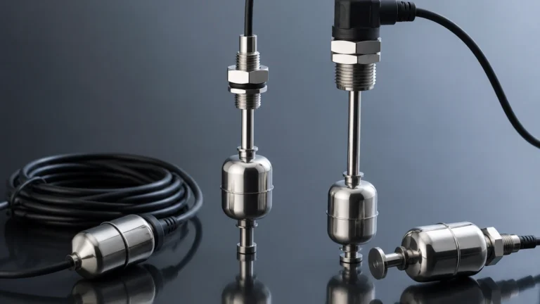
Level Float
Level Float
In the landscape of industrial process control, the level float remains one of the most enduring and reliable technologies for liquid level measurement. Despite the advent of non-contact technologies like radar and ultrasonic sensors, float-based systems are preferred in many B2B applications due to their inherent simplicity, high accuracy, and immunity to certain environmental factors such as foam, vapor, and dust. This guide provides a comprehensive technical overview of level float principles, selection criteria, and installation best practices for engineering and procurement professionals.
Measurement Principles of Level Float Systems
The operation of any level float device is governed by Archimedes' Principle, which states that a body immersed in a fluid is buoyed up by a force equal to the weight of the fluid displaced by the body. In practical level measurement, a float is designed with a specific density lower than that of the process liquid, ensuring it remains partially submerged at the liquid-gas interface.
Mechanical and Magnetic Coupling
There are two primary methods by which the position of a float is converted into a readable signal:
1. Direct Mechanical Linkage: Used primarily in simple float switches or small tank indicators, where the float's movement physically toggles a microswitch or moves a pointer.
2. Magnetic Coupling: This is the standard for modern industrial applications. The float contains an internal permanent magnet. As the float moves along a guide tube (stem), the magnetic field interacts with sensors located inside the tube.
Sensing Technologies within the Stem
In continuous level transmitters, the stem typically houses a series of reed switches and resistors. As the float moves, its magnetic field closes specific reed switches, changing the total resistance of the circuit. This change is converted into a standard 4-20mA signal or a digital output. For point-level detection (float switches), the magnet simply triggers a single reed switch at a predetermined height to signal a high or low level alarm.
Types of Level Float Instruments
Understanding the distinction between different float-based instruments is essential for correct project specification. For a complete range of industrial measurement tools, engineers often Review product options and application support to match specific tank geometries with the right sensor type.
1. Magnetic Level Float Switches
These are used for point-level detection. They are ideal for pump control, overflow protection, and dry-run prevention. They can be mounted vertically or horizontally. Multi-point switches allow for several trigger levels (e.g., Low-Low, Low, High, High-High) within a single mounting flange.
2. Continuous Float Level Transmitters
These provide a constant level reading, typically with an accuracy of ±5mm to ±10mm. They are used when the exact volume of a tank needs to be monitored in real-time. Because they rely on a resistive chain, the resolution is determined by the spacing of the reed switches inside the stem.
3. Magnetic Level Gauges (Bypass Indicators)
In this configuration, the float resides in a bypass chamber mounted to the side of the vessel. The float's magnet interacts with external magnetic flaps (flags) or a follower on a scale. This provides a highly visible local indication without the need for power, while also allowing for the attachment of electronic transmitters for remote monitoring.
Technical Selection Criteria
Selecting the correct level float requires a detailed analysis of the process medium and the vessel environment. The following table outlines the primary material and design considerations:
Selection Table: Material and Application Suitability
| Material | Temperature Range | Max Pressure | Typical Applications |
| :— | :— | :— | :— |
| Stainless Steel (304/316L) | -40°C to +250°C | Up to 40 bar | Oil, fuels, high-temperature water, food processing. |
| Polypropylene (PP) | -10°C to +80°C | Up to 3 bar | Acids, alkalis, wastewater, general chemical storage. |
| PVDF / PTFE | -20°C to +120°C | Up to 6 bar | Highly aggressive chemicals, ultra-pure water. |
| PVC | 0°C to +60°C | Up to 2 bar | Low-cost water treatment, irrigation. |
Specific Gravity (SG) Considerations
The float must be lighter than the liquid it is measuring. Most standard industrial floats are designed for liquids with an SG of 0.8 or higher. If measuring light hydrocarbons or liquefied gases with an SG of 0.5 to 0.7, a specialized high-buoyancy float (often made of titanium or thin-walled stainless steel) is required. If the liquid density changes significantly due to temperature fluctuations, the float's immersion depth will change, leading to measurement errors.
Engineering Installation and Calibration
Proper installation is critical to ensure the longevity of a level float sensor and to prevent mechanical failure.
Mounting Orientation
Vertical installation is the most common for continuous transmitters. The stem must be perfectly plumb to prevent the float from binding against the tube. For horizontal float switches, ensure the pivot point is clear of any internal tank structures.
Dealing with Turbulence
In tanks with agitators or high-velocity inflow, the lateral force of the liquid can bend the sensor stem or cause the float to chatter, leading to premature wear. In these scenarios, a stilling well (a perforated pipe surrounding the sensor) should be installed to provide a calm surface for the float.
Clearance Requirements
* Bottom Clearance: Ensure there is enough space at the bottom of the tank so the float does not hit the floor before the liquid is empty.
* Nozzle Diameter: The mounting nozzle must be wide enough to allow the float to pass through during installation. If the float is larger than the nozzle, it must be attached to the stem from inside the tank.
Calibration
Most magnetic float transmitters are factory-calibrated. However, field calibration of the 4-20mA loop is often necessary to align the 0% and 100% points with the actual tank bottom and overflow levels. Unlike radar sensors, float sensors do not require complex software configuration; they simply require the setting of the current output relative to the float's position.

Limitations and Application Risks
While highly versatile, level float technology is not suitable for every application. Engineers should be aware of the following limitations:
1. Viscosity and Coating: High-viscosity liquids or those that tend to crystallize can cause the float to stick to the stem. If the medium is "sticky," non-contact measurement is usually a better choice.
2. Particulate Matter: Large solids or fibrous materials in the liquid can jam the float. This is a common issue in raw sewage or pulp processing.
3. Mechanical Wear: Because it is a moving-part technology, the float and the reed switches have a finite mechanical life. In high-vibration environments, the reed switches may fail prematurely.
4. Pressure Limits: At very high pressures, thin-walled floats can collapse. For high-pressure boiler applications, heavy-duty spherical floats or magnetic level gauges with thick-walled chambers are required.
Industry-Specific Applications
Water and Wastewater Treatment
Level floats are ubiquitous in pump lift stations. Because they are unaffected by the steam and foam often found in wastewater, they provide a fail-safe method for controlling submersible pumps. Typically, a series of suspended cable float switches are used here for extreme durability.
Chemical Processing
In chemical dosing tanks, PVDF or PTFE-coated float transmitters offer excellent resistance to corrosive reagents. The closed-loop nature of the magnetic coupling ensures that the electronic components are never in contact with the aggressive vapors, enhancing safety and instrument life.
Oil and Gas Storage
For fuel storage tanks, stainless steel float transmitters are preferred for their fire resistance and compatibility with hydrocarbons. They are often paired with explosion-proof (Ex d) or intrinsically safe (Ex i) housings to meet hazardous area requirements.
Frequently Asked Questions (FAQ)
Q: Can a level float be used in pressurized tanks?
A: Yes, but the float must be rated for the specific pressure. Standard stainless steel floats can often handle up to 20-40 bar (approx. 290-580 psi). For higher pressures, specialized designs are necessary.
Q: How do I maintain a float level sensor?
A: Maintenance primarily involves periodic inspection for buildup on the stem or float. In clean water applications, this may only be needed once a year. In dirtier environments, a monthly check to ensure the float moves freely is recommended.
Q: What is the difference between a float switch and a float transmitter?
A: A float switch provides a discrete output (on/off) at a specific level, whereas a float transmitter provides a continuous signal (e.g., 4-20mA) representing the exact level across a range.
Q: Can I use a float sensor for interface measurement (e.g., oil on top of water)?
A: Yes. By weighting the float so that its density is between that of the two liquids (e.g., higher than oil but lower than water), the float will sink through the top layer and float on the interface layer.
Conclusion
The level float remains a cornerstone of industrial liquid management due to its straightforward physics and ease of integration. By carefully considering liquid density, chemical compatibility, and tank dynamics, engineers can implement float-based solutions that provide decades of reliable service. For those requiring detailed specifications or customized OEM solutions, the Main Page of professional manufacturers provides the necessary technical documentation to ensure project success.