Fluid Level Sensors
Fluid Level Sensors
In the landscape of industrial automation and process control, fluid level sensors serve as critical components for ensuring operational safety, inventory management, and process efficiency. From monitoring water levels in municipal treatment plants to managing volatile chemicals in high-pressure reactors, the selection of the correct sensing technology is a fundamental engineering decision. As a professional manufacturer, Welk provides a comprehensive range of instruments designed to meet these diverse industrial requirements, ensuring that every application is matched with a reliable and accurate measurement solution.
Selecting the appropriate instrument requires a deep understanding of the underlying physical principles, the characteristics of the fluid being measured, and the environmental conditions of the installation site. For technical specifications and product comparisons, engineers often refer to the Main Page to evaluate which technology aligns with their specific process parameters.
Measurement Principles and Technologies
Fluid level sensors are broadly categorized into non-contact and contact measurement methods. Each technology utilizes different physical properties—such as sound waves, electromagnetic waves, or hydrostatic pressure—to determine the level of a liquid within a vessel.
Radar Level Measurement (Non-Contact)
Radar level sensors utilize high-frequency electromagnetic waves, typically in the 26GHz or 80GHz range. The sensor emits a signal that travels to the liquid surface, reflects, and returns to the receiver.
There are two primary methods used in radar sensing:
1. Pulse Radar: Measures the time-of-flight of a short microwave pulse.
2. Frequency Modulated Continuous Wave (FMCW): Emits a continuous signal with a varying frequency. The difference in frequency between the emitted and received signal is proportional to the distance.
Radar is highly valued because it is independent of changes in density, temperature, or pressure. 80GHz radar, in particular, offers a narrow beam angle, which is ideal for avoiding internal tank obstructions like agitators or heating coils.
Ultrasonic Level Measurement (Non-Contact)
Ultrasonic fluid level sensors operate by emitting high-frequency sound pulses (usually 20 kHz to 200 kHz). The sensor measures the time it takes for the echo to return from the fluid surface.
Since the speed of sound is affected by air temperature, these sensors typically include an integrated temperature sensor to perform real-time compensation. Ultrasonic sensors are cost-effective and highly effective for water and wastewater applications, though they can be affected by heavy foam, steam, or significant dust, which may absorb or scatter the sound waves.
Hydrostatic Level Measurement (Contact)
Hydrostatic transmitters measure the level of a fluid by sensing the pressure exerted by the liquid column at a specific depth. The relationship follows the formula: $P = \rho \cdot g \cdot h$, where $P$ is pressure, $\rho$ is the fluid density, $g$ is gravity, and $h$ is the height of the liquid.
These sensors are usually submersible or mounted to the bottom of a tank via a flange. They are exceptionally reliable for deep wells and open reservoirs. However, because they rely on density, any significant change in the fluid's temperature or composition (which affects density) will require recalibration to maintain accuracy.
Magnetic Level Gauges (Contact)
Magnetic level gauges consist of a bypass chamber attached to the side of a vessel. Inside the chamber, a float containing a permanent magnet moves up and down with the fluid level. Outside the chamber, a visual indicator (typically magnetic flaps) or a reed-switch transmitter tracks the position of the float. This provides both a local visual reading and an electronic output for remote monitoring without the sensor ever coming into direct electrical contact with the fluid.
Practical Selection Table
When choosing between different fluid level sensors, engineers must balance performance requirements against budget and environmental constraints. The following table provides a general comparison of the most common technologies.
| Technology | Typical Accuracy | Max Range (Metric) | Media Compatibility | Relative Cost |
| :— | :— | :— | :— | :— |
| 80GHz Radar | ±2 mm | 120 meters | Corrosive, High Temp, Agitated | High |
| Ultrasonic | ±0.25% of range | 30 meters | Water, Acids, Bases | Medium |
| Hydrostatic | ±0.1% to 0.5% | 200 meters | Clean Liquids, Slurries | Low to Medium |
| Magnetic Gauge| ±5 mm | 6 meters | High Pressure, Toxic Fluids | Medium |
| Level Switch | N/A (Point Level) | N/A | Almost all fluids | Low |
Installation Considerations
Correct installation is as vital as selecting the right technology. Even the most advanced sensor will fail to provide accurate data if environmental factors are ignored.
1. Dead Zones (Blocking Distance): Every non-contact sensor has a "dead zone" directly beneath the transducer face where it cannot measure. For ultrasonic sensors, this is typically 0.25m to 0.6m (approx. 10 to 24 inches). Ensure the sensor is mounted high enough so the fluid never enters this zone.
2. Mounting Position: Sensors should be mounted away from the tank wall to prevent signal interference from weld seams or build-up. For radar and ultrasonic types, the beam should be perpendicular to the liquid surface. Avoid mounting directly above the fluid inlet, as the turbulence and falling liquid will cause erratic readings.
3. Stilled Pipes and Bypass Chambers: In tanks with heavy agitation or surface foam, installing the sensor inside a stilling well or a bypass pipe can provide a calm surface for measurement, significantly increasing the reliability of the data.
4. Atmospheric Venting: For hydrostatic sensors measuring open tanks, the reference side of the pressure diaphragm must be vented to the atmosphere (usually via a vent tube in the cable) to compensate for changes in barometric pressure.
Limitations and Environmental Constraints
While modern fluid level sensors are robust, they are not universal. Understanding their limitations prevents project failures.
* Dielectric Constant (εr): Radar sensors rely on the dielectric constant of the fluid to reflect waves. Fluids with very low dielectrics, such as certain oils or liquefied gases (εr < 2.0), reflect very little energy, requiring specialized high-sensitivity radar units or guided wave radar (GWR).
* Vacuum Conditions: Ultrasonic sensors cannot function in a vacuum because sound waves require a medium (air/gas) to travel. In such cases, radar or hydrostatic sensors must be used.
* Temperature Extremes: Ultrasonic transducers are generally limited to temperatures below 80°C (176°F). For high-temperature steam or molten materials, high-frequency radar with specialized cooling fins or heat-resistant seals is required.
* Foam and Turbulence: Thick, dense foam can act as an insulator for ultrasonic waves, leading to a "lost echo" error. Radar is generally more resistant to foam, but extremely thick protein-based foams may still pose challenges.
Application Scenarios
Water and Wastewater Treatment
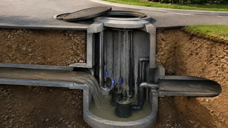
In this sector, ultrasonic sensors are the standard for monitoring open channel flow and tank levels due to their non-contact nature and resistance to the corrosive gases often found in sewage. Hydrostatic sensors are preferred for deep well level monitoring and lift stations where the sensor must be submerged.
Chemical Processing
Chemical tanks often contain aggressive media like sulfuric acid or sodium hydroxide. Here, non-contact radar sensors with PTFE (Teflon) wetted parts are preferred to prevent corrosion. For toxic or high-pressure chemicals, magnetic level gauges are often used because they provide a physical barrier between the process and the observer.
Oil and Gas
Measurement in the oil and gas industry involves high pressures and varying densities. Guided wave radar (GWR) is frequently used for interface measurement (e.g., the line between oil and water in a separator tank) because it can detect the change in dielectric constant between the two liquid layers.
Frequently Asked Questions (FAQ)
Q: How do I choose between 26GHz and 80GHz radar?
A: 80GHz radar is generally superior for small tanks or vessels with many internal obstructions because it has a much narrower beam. 26GHz radar is often sufficient for large, open storage tanks and can be more cost-effective for simpler applications.
Q: Can fluid level sensors measure solids?
A: Yes, but with caveats. Radar and ultrasonic sensors can measure powders and grains, but the "angle of repose" (the slope of the material) can deflect the signal. Specialized solids-handling versions of these sensors are usually required.
Q: Does the shape of the tank affect the measurement?
A: For level (height), the shape does not matter. However, if you need to calculate volume (liters or gallons), the sensor or the control system must be programmed with a tank strapping table or a geometric formula to account for horizontal cylinders, spherical bottoms, or tapered walls.
Q: How often do fluid level sensors need calibration?
A: This depends on the technology. Hydrostatic sensors should be checked annually for drift. Non-contact radar sensors are extremely stable and may only need verification every 2-3 years, depending on the criticality of the process.
Conclusion for Engineering Procurement
Selecting the right fluid level sensor is a balance of physics and practical constraints. By understanding the dielectric properties, pressure requirements, and physical layout of the tank, engineers can avoid common pitfalls such as signal loss or premature sensor failure. Welk continues to innovate in this space, providing the technical expertise and hardware necessary to solve the most challenging level measurement problems. For further technical documentation and to view our full product catalog, please visit our Main Page.