Tank Level Sensor
Tank Level Sensor
In industrial process automation, the accurate monitoring of liquids and solids within storage vessels is a foundational requirement for safety, inventory management, and process efficiency. A tank level sensor is a device designed to measure the height of a substance—be it water, chemicals, fuel, or granular solids—relative to a reference point, typically the bottom of the tank. These instruments convert the physical level into an electrical signal, such as 4-20mA, RS485 Modbus, or HART, which is then transmitted to a control system or display.
Selecting the appropriate technology requires a deep understanding of measurement principles, fluid characteristics, and environmental constraints. As a professional manufacturer, Welk provides a comprehensive range of solutions including radar, ultrasonic, and hydrostatic instruments to meet these diverse industrial needs. This guide serves as a practical engineering reference for evaluating and implementing the correct level measurement technology.
Core Measurement Principles
Before selecting a tank level sensor, it is essential to understand the physics behind the various measurement methods. Industrial level sensors are generally categorized into non-contact and contact technologies.
1. Radar Level Measurement (Non-Contact)
Radar level sensors operate using electromagnetic waves, typically in the microwave frequency range (e.g., 26GHz or 80GHz). There are two primary types: Pulse Radar and Frequency Modulated Continuous Wave (FMCW).
* Principle: The sensor emits a high-frequency signal toward the product surface. The signal reflects off the surface and returns to the antenna. The distance ($d$) is calculated using the Time of Flight (ToF) formula: $d = (c \times t) / 2$, where $c$ is the speed of light and $t$ is the elapsed time. FMCW radar, which is increasingly common, measures the frequency shift between the emitted and received signal to provide higher precision.
* Advantages: It is unaffected by temperature, pressure, vacuum, or dust. It is ideal for corrosive or high-temperature environments because the sensor does not touch the medium.
2. Ultrasonic Level Measurement (Non-Contact)
Ultrasonic sensors utilize sound waves rather than electromagnetic waves.
* Principle: The transducer emits an ultrasonic pulse (typically 20kHz to 70kHz). This pulse reflects off the liquid surface and returns to the sensor. The distance is calculated based on the speed of sound in air. Since the speed of sound varies with air temperature, these sensors usually include an integrated temperature sensor for compensation.
* Advantages: This is a cost-effective solution for standard water and wastewater applications. It is easy to install and maintain due to the lack of moving parts.
3. Hydrostatic Level Measurement (Contact)
Hydrostatic sensors, also known as submersible pressure transmitters, rely on the weight of the liquid column.
* Principle: The sensor measures the static pressure exerted by the liquid at a specific depth. The relationship is defined by the formula: $P = \rho \cdot g \cdot h$, where $P$ is pressure, $\rho$ is the density of the liquid, $g$ is gravity, and $h$ is the height of the liquid.
* Advantages: These are highly reliable for deep tanks, reservoirs, and boreholes. They are simple to install by lowering the probe to the bottom of the vessel.
4. Magnetic Level Gauges (Contact)
Magnetic gauges provide both local visual indication and electronic feedback.
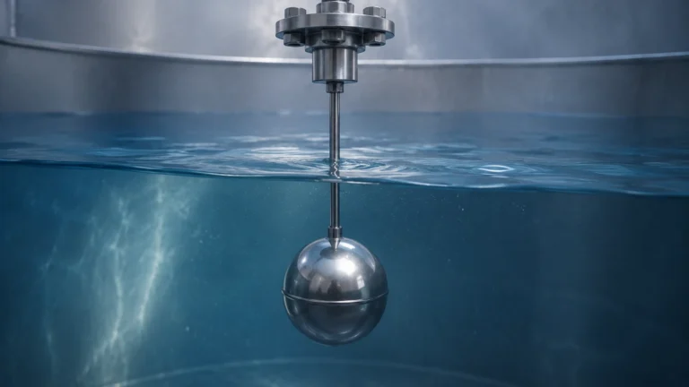
* Principle: A float containing a permanent magnet moves up and down within a bypass chamber connected to the tank. As the float moves, it flips magnetic flags on an external scale for visual reading. For electronic output, a reed chain or magnetostrictive transmitter is mounted to the chamber.
* Advantages: They provide a clear visual reference without requiring power and are excellent for high-pressure or high-temperature hazardous liquids.
Engineering Selection Criteria
Choosing the right tank level sensor is not a one-size-fits-all process. Engineers must confirm several technical parameters before finalizing a specification.
Fluid Characteristics
* Dielectric Constant ($ε_r$): For radar sensors, the reflectivity of the signal depends on the dielectric constant of the medium. Low $ε_r$ fluids (like hydrocarbons) reflect less energy than high $ε_r$ fluids (like water).
* Density: Hydrostatic sensors are density-dependent. If the liquid density changes due to temperature fluctuations or mixing, the level reading will drift unless compensated.
* Corrosiveness: For aggressive chemicals, non-contact sensors or sensors with PTFE/PVDF wetted parts are required.
Process Conditions
* Temperature and Pressure: High-pressure tanks (e.g., >40 bar / 580 psi) often require specialized radar or magnetic gauges. Ultrasonic sensors are generally limited to atmospheric or low-pressure vessels.
* Vapor and Foam: Heavy steam or thick foam can absorb ultrasonic signals, leading to signal loss. In such cases, high-frequency radar (80GHz) or guided wave radar is preferred.
* Turbulence: Agitators and mixers create surface turbulence. Software filtering and damping are necessary to ensure a stable reading.
Tank Geometry
* Internal Obstructions: Ladders, heating coils, and inlet pipes can create false echoes for radar and ultrasonic sensors. Modern sensors use "false echo suppression" to map out these obstructions.
* Mounting Location: Sensors should generally not be mounted in the center of a tank (to avoid multiple reflections) or too close to the wall (to avoid side-lobe interference).
Technical Comparison Table
| Feature | Radar (80GHz) | Ultrasonic | Hydrostatic | Magnetic Gauge |
| :— | :— | :— | :— | :— |
| Measurement Type | Non-contact | Non-contact | Contact (Pressure) | Contact (Float) |
| Accuracy | ±1 mm to ±2 mm | ±0.25% of range | ±0.1% to ±0.5% | ±5 mm to ±10 mm |
| Max Range | Up to 120 m (393 ft) | Up to 15 m (49 ft) | Up to 200 m (656 ft) | Up to 6 m (20 ft) |
| Pressure Limit | High (up to 160 bar) | Atmospheric | High (Submersible) | High (up to 320 bar) |
| Temp. Limit | -40°C to +450°C | -40°C to +80°C | -20°C to +80°C | -196°C to +400°C |
| Best For | Chemical/Oil & Gas | Water Treatment | Deep Wells/Open Tanks | Boiler/Toxic Media |
Installation Best Practices
Proper installation is as critical as selecting the right technology. Failure to follow manufacturer guidelines often leads to "dead zones" or erratic readings.
1. Avoid the Fill Stream: Never install a tank level sensor directly above the inlet pipe. The falling liquid will interfere with the signal or cause physical damage to the probe.
2. Nozzle Height and Diameter: For radar and ultrasonic sensors, ensure the nozzle is short enough that it does not interfere with the signal beam angle. A standard 10° beam angle requires specific clearance.
3. Stilling Wells: In tanks with heavy turbulence or foam, installing the sensor inside a stilling well (a vertical pipe) can provide a calm surface for accurate measurement.
4. Venting for Hydrostatic Probes: Hydrostatic sensors use a vented cable to compensate for atmospheric pressure changes. Ensure the vent tube is not kinked and is protected by a moisture filter.
5. Grounding: In industrial environments with heavy machinery, ensure the sensor housing is properly grounded to prevent EMI (Electromagnetic Interference) from distorting the signal.
For more detailed technical specifications and to Review product options and application support, engineers should consult the Main Page of the manufacturer's technical documentation.
Operational Limitations and Risks
While modern tank level sensors are highly advanced, they are not infallible. Users should be aware of the following risks:
* The Blocking Distance (Dead Zone): All ultrasonic and radar sensors have a minimum distance near the transducer where they cannot measure. If the tank overfills into this zone, the sensor may report a full or empty error.
* Build-up and Coating: In sticky applications (like wastewater or resin), material can build up on the sensor face. While some radar sensors can "see through" thin coatings, heavy build-up will eventually cause signal failure.
* Vacuum Effects: Ultrasonic sensors cannot operate in a vacuum because sound waves require a medium (air/gas) to travel. Radar is the only non-contact option for vacuum tanks.
* Gas Composition Changes: If the gas layer above the liquid changes (e.g., from air to Nitrogen or CO2), the speed of sound changes, which will cause an ultrasonic sensor to provide an incorrect reading unless it is recalibrated for the new gas density.
Frequently Asked Questions (FAQ)
Q: Can I use one sensor for both liquids and solids?
A: Generally, radar sensors are better suited for solids because they can handle the low dielectric constant and the angled surfaces of grain or powder piles. Ultrasonic sensors struggle with the uneven reflection angles of solids.
Q: How often do tank level sensors need calibration?
A: This depends on the technology. Hydrostatic sensors may drift over time and should be checked annually. Radar and ultrasonic sensors are digital and typically do not require recalibration unless the process conditions change significantly.
Q: What is the difference between 2-wire and 4-wire sensors?
A: 2-wire sensors use the same pair of wires for both power and the 4-20mA signal, making them easier to wire. 4-wire sensors have separate power and signal wires, which is often necessary for high-power devices like heated radar units or those with large backlit displays.
Q: Is it possible to measure level in a plastic tank from the outside?
A: Yes, certain high-frequency radar sensors can transmit through the plastic wall of a tank to measure the liquid inside, provided the plastic is not carbon-filled or metallic-lined.
Conclusion
Selecting a tank level sensor requires balancing technical requirements with budget constraints. While ultrasonic sensors offer a cost-effective solution for simple water applications, radar technology provides the versatility needed for complex chemical and high-temperature processes. By understanding the measurement principles and accounting for environmental factors like foam, pressure, and tank geometry, engineers can ensure long-term reliability and accuracy. For comprehensive technical data and to explore specific models, visiting the Main Page of a dedicated manufacturer like Welk is the recommended next step for procurement and system design.