Level Guard Sump Pump Switch
Level Guard Sump Pump Switch
In industrial and commercial water management, the reliability of a sump pump system is almost entirely dependent on its control mechanism. While the pump provides the mechanical force to move fluid, the level switch serves as the primary intelligence, determining exactly when the system should activate and deactivate. For facilities managing wastewater, cooling tower runoff, or elevator pit drainage, the failure of a switch can lead to significant property damage, environmental non-compliance, and operational downtime. Among the various technologies available, the level guard sump pump switch has emerged as a preferred solution for applications where traditional mechanical floats are prone to failure.
This guide examines the engineering principles behind sump pump switches, compares solid-state technology with mechanical alternatives, and provides a framework for selecting and installing these critical components in industrial environments.
Understanding Level Measurement Principles
Before selecting a specific switch, it is essential to understand the physical principles that govern level detection. In the context of sump management, three primary sensing methods are commonly employed: mechanical buoyancy, conductivity, and capacitance.
Mechanical Buoyancy
Traditional float switches rely on Archimedes' principle. A buoyant object (the float) rises with the liquid level until it reaches a mechanical tipping point, which then closes a microswitch or moves a metal ball to complete an electrical circuit. While cost-effective, these systems are vulnerable to "hang-ups" where the float becomes snagged on discharge pipes, pump power cords, or debris within the sump pit.
Conductivity Sensing
Conductivity switches use two or more electrodes. When the liquid (which must be electrically conductive) touches the probes, a low-voltage circuit is completed, signaling the pump to start. These are highly reliable but can be affected by electrode fouling or the presence of non-conductive coatings like oils or fats.
Capacitance and Solid-State Sensing
The level guard sump pump switch typically utilizes solid-state or capacitive sensing. This technology detects the presence of liquid by measuring the change in electrical capacitance or field strength at the sensor's surface. Because there are no moving parts, the sensor is immune to the mechanical wear, corrosion, and physical obstructions that plague float-based systems. This "solid-state" approach allows the switch to be mounted directly to the discharge pipe or the wall of the pit, significantly reducing the footprint required for operation.
The Evolution of Sump Pump Switches: Mechanical vs. Electronic
For decades, the tethered float was the industry standard. However, as industrial sumps became smaller and more crowded with piping and backup pumps, the failure rate of mechanical switches increased. The level guard sump pump switch was developed to address these specific failure modes.
| Feature | Mechanical Tethered Float | Vertical Mechanical Float | Solid-State (Level Guard) |
| :— | :— | :— | :— |
| Moving Parts | Yes | Yes | No |
| Space Requirement | Large (Swing radius) | Moderate (Vertical travel) | Minimal (Surface mount) |
| Debris Resistance | Low | Moderate | High |
| Reliability | Moderate | Moderate | Very High |
| Switching Life | ~100,000 cycles | ~250,000 cycles | >1,000,000 cycles |
| Failure Mode | Mechanical snagging | Shaft corrosion/sticking | Electronic component aging |
In many high-stakes industrial applications, engineers are moving away from mechanical components toward solid-state solutions. For more complex tank environments requiring continuous monitoring rather than simple point-level switching, professionals often consult the Main Page of specialized manufacturers like Welk to evaluate radar or ultrasonic alternatives.
Technical Deep-Dive: Solid-State Sensing
A level guard sump pump switch operates using a pair of sensors that detect the liquid level. The "Start" sensor is positioned at the desired high-water mark, and the "Stop" sensor is at the low-water mark.
1. Detection: When water reaches the upper sensor, the solid-state circuitry detects the change in the electrical field.
2. Activation: The switch engages an internal relay or a power plug that provides current to the pump.
3. Latching: The switch remains active even after the water falls below the upper sensor (a process known as latching) until the water level drops below the lower sensor.
4. Deactivation: Once the lower sensor is dry, the circuit opens, and the pump stops.
This dual-point sensing prevents "short-cycling," where a pump turns on and off rapidly due to surface turbulence, which can overheat the pump motor and lead to premature failure.
Selection Criteria for Industrial Sump Applications
When specifying a level guard sump pump switch for a B2B or industrial environment, the following criteria must be confirmed:
1. Electrical Load and Rating
Most solid-state switches are rated for specific horsepower (HP) or amperage. A common rating for industrial-grade switches is 120V/240V AC at 10A to 15A. It is critical to ensure the switch can handle the pump's "in-rush" current (the surge of electricity when the motor starts). If the pump exceeds the switch's rating, an external power relay or motor starter must be used.
2. Media Compatibility
While designed for water, industrial sumps often contain secondary fluids. If the sump contains high concentrations of oils, grease, or aggressive chemicals, the sensor material must be verified. Solid-state switches are generally excellent for water and mild wastewater but may require specialized coatings for caustic environments.
3. Temperature Range
Standard switches are typically rated for operation between 0°C and 50°C (32°F to 122°F). In applications involving hot condensate or industrial boiler blowdown, high-temperature variants or hydrostatic transmitters may be required.
4. Mounting Configuration
Industrial pits vary in geometry. Ensure the switch includes robust mounting hardware, such as stainless steel pipe clamps or wall-mount brackets. The ability to adjust the "on" and "off" points by moving the sensors independently is a significant advantage in deep sumps.
Installation Best Practices
Proper installation is as important as the technology itself. Follow these engineering guidelines to ensure long-term reliability:
* Positioning: Mount the sensors away from the direct path of the incoming water (the "inlet"). Turbulence or splashing can cause false triggers or erratic pump behavior.
* Clearance: Although solid-state switches do not move, they should still be mounted with at least 50 mm (2 inches) of clearance from metal pipes or walls to prevent interference with the capacitive field, unless the specific model is designed for direct contact.
* Wiring Protection: In industrial settings, cables should be run through conduit to protect against physical damage and chemical exposure. Ensure the plug connections are kept in a dry, NEMA-rated enclosure.
* Grounding: Ensure the pump and the switch are properly grounded to prevent electrical noise from interfering with the solid-state sensors.
Comparison of Level Measurement Technologies
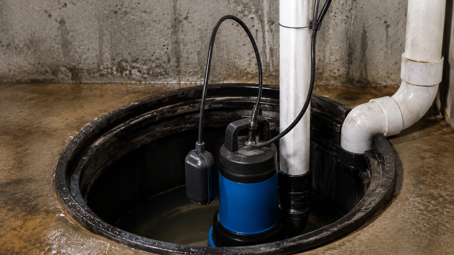
For facilities managers deciding between a basic switch and a more advanced level measurement system, the following table provides a comparison of common industrial technologies used in sump and tank management.
| Technology | Typical Use Case | Accuracy | Maintenance Level |
| :— | :— | :— | :— |
| Level Guard Switch | Sump pits, elevator vaults | High (Point level) | Very Low |
| Hydrostatic Pressure | Deep wells, large tanks | High (Continuous) | Moderate (Probe cleaning) |
| Ultrasonic (Non-contact) | Chemical tanks, open channels | Very High | Low |
| Radar (80GHz) | Aggressive media, foam/steam | Extremely High | Very Low |
For applications requiring high-precision continuous data rather than point-level switching, Welk offers advanced radar and ultrasonic level meters that integrate directly with SCADA and PLC systems. You can review these advanced product options on the Main Page.
Limitations and Operational Constraints
While the level guard sump pump switch is highly reliable, it is not a universal solution for every fluid management challenge. Professionals should be aware of the following limitations:
1. Coating and Scaling: If the fluid is prone to heavy mineral scaling or thick grease buildup, the sensor surface may eventually become insulated. Periodic wiping of the sensor face is recommended in these environments.
2. Non-Conductive Fluids: In extremely pure deionized water or certain hydrocarbons, some solid-state switches may struggle to detect the level change. Capacitive sensors are generally better for these than conductivity-based ones.
3. High Solids Content: In sumps handling heavy sludge or large solids, the physical presence of debris can still interfere with the sensor if it becomes trapped against the sensing face.
Maintenance and Troubleshooting
One of the primary benefits of the level guard sump pump switch is its low maintenance requirement. However, a quarterly inspection protocol is recommended for industrial facilities:
* Visual Inspection: Check the sensor face for any buildup of grease, hair, or mineral deposits. Clean with a soft cloth and mild detergent if necessary.
* Manual Trigger Test: Fill the sump with water to verify the "Start" point and ensure the pump runs until the "Stop" point is reached.
* Cable Integrity: Inspect the power cord for signs of cracking, brittleness, or chemical degradation, especially near the entry point of the pit.
FAQs
Q: Can a level guard switch be used with a battery backup pump?
A: Yes, provided the voltage and current ratings match. Many solid-state switches are available in 12V DC versions specifically for backup systems.
Q: What happens if the power goes out?
A: Like all electronic switches, the level guard requires power to function. In critical applications, it is standard practice to use a redundant mechanical float as a high-level alarm or to have the system connected to an Uninterruptible Power Supply (UPS).
Q: Can I use this switch in a sewage basin?
A: Yes, solid-state switches are excellent for sewage because they do not have a float that can get stuck on "solids." However, ensure the model is rated for the specific environment and that the sensors are cleaned periodically to prevent grease buildup.
Q: How do I adjust the pumping range?
A: With a level guard sump pump switch, the range is typically adjusted by changing the vertical distance between the high and low sensors. Increasing this distance reduces the frequency of pump starts, extending the motor life.
Conclusion
The transition from mechanical to solid-state level detection represents a significant upgrade in industrial sump reliability. By eliminating moving parts, the level guard sump pump switch solves the most common cause of sump pump failure: the stuck float. For engineers and facility managers, selecting the right switch involves a careful assessment of electrical loads, fluid characteristics, and pit geometry. While solid-state switches are ideal for point-level control in sumps, broader industrial applications involving complex tanks or chemical processing may benefit from the wide range of radar, ultrasonic, and hydrostatic instruments available from professional manufacturers like Welk. For comprehensive technical specifications and to explore the full range of industrial level measurement solutions, visit the Main Page.