Coriolis Sensor
Coriolis Sensor
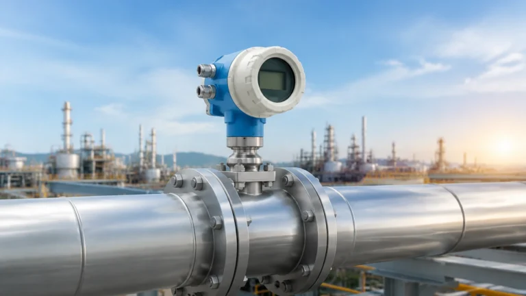
In the landscape of industrial process control, the Coriolis sensor represents the pinnacle of mass flow and density measurement technology. Unlike volumetric flow meters that require compensation for temperature and pressure, a Coriolis sensor measures mass directly, providing an exceptionally high degree of accuracy and stability. For engineers and plant managers focused on inventory management and process efficiency, understanding the integration of these sensors into broader measurement systems is essential for achieving precise level and mass balance control.
While primarily recognized as a flow measurement device, the Coriolis sensor plays a critical role in modern level measurement strategies, particularly in applications where fluid density varies or where mass-based inventory is the primary metric. This guide explores the engineering principles, selection criteria, and installation requirements for Coriolis sensors within industrial environments.
Fundamental Principles of Coriolis Measurement
The operation of a Coriolis sensor is based on the principles of motion physics, specifically the Coriolis effect. This effect describes the inertial force acting on an object that moves within a rotating frame of reference. In an industrial sensor, this "rotation" is simulated through high-frequency oscillation.
The Coriolis Effect in Practice
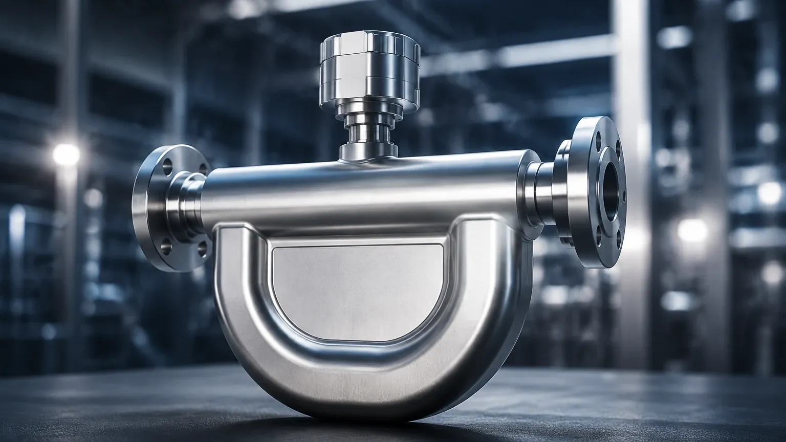
A typical Coriolis sensor consists of one or more measuring tubes that are vibrated at their resonant frequency by an electromagnetic drive coil. When there is no flow, the tubes vibrate in a uniform, symmetrical manner. However, when a fluid (liquid or gas) flows through these vibrating tubes, it experiences a Coriolis acceleration.
As the fluid moves toward the point of maximum vibration amplitude, it resists being pushed upward and pushes down on the tube. Conversely, as the fluid moves away from the peak, it resists having its vertical motion decreased and pushes up on the tube. This creates a twisting motion, or phase shift, across the length of the tube. The magnitude of this phase shift is directly proportional to the mass flow rate of the medium. Because mass is an intrinsic property that does not change with temperature or pressure, the measurement remains accurate regardless of changing process conditions.
Simultaneous Density Measurement
Beyond mass flow, the Coriolis sensor is an exceptionally accurate densitometer. The tubes vibrate at their natural resonant frequency, which is a function of the mass of the tube and the mass of the fluid inside it. As the density of the fluid changes, the total mass of the system changes, shifting the resonant frequency. By measuring this frequency, the sensor can calculate the real-time density of the medium. This dual capability makes the Coriolis sensor a vital component in applications requiring concentration measurement (e.g., Brix or Plato scales) and mass-to-volume conversions.
Key Components and System Architecture
A complete Coriolis measurement system generally consists of two primary elements: the sensor (the wetted part) and the transmitter (the electronics).
1. Measuring Tubes: These are the heart of the sensor. They are typically constructed from stainless steel (316L), Hastelloy, or titanium to withstand corrosive media. Geometries vary from U-shaped to straight-tube designs.
2. Drive Coil and Pick-offs: The drive coil maintains the tube's oscillation, while electromagnetic pick-off sensors located at the inlet and outlet sides detect the phase shift and frequency.
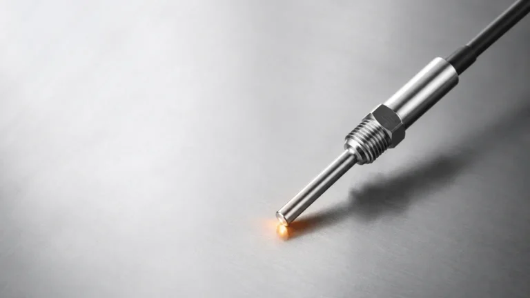
3. Temperature Sensor: An internal RTD (Resistance Temperature Detector) measures the tube temperature. This is used to compensate for changes in the tube's elasticity caused by thermal fluctuations, ensuring the spring constant remains calibrated.
4. Transmitter: The transmitter processes the raw signals from the pick-offs, performs the complex mathematical calculations for flow and density, and provides outputs such as 4-20mA, HART, Modbus, or Profibus.
For comprehensive system integration, engineers often refer to the Main Page of instrumentation providers to ensure compatibility between flow, level, and pressure components.
Integrating Coriolis Sensors with Level Measurement Systems
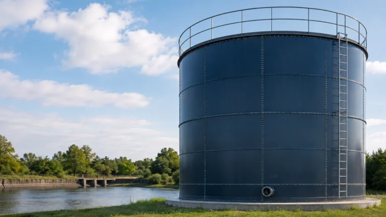
In many industrial sectors, such as chemical processing and oil and gas, level measurement is not just about the height of the liquid; it is about the total mass in the vessel. Integrating a Coriolis sensor into the supply or discharge lines of a storage tank allows for a "mass balance" approach to level monitoring.
Mass Balance vs. Volumetric Level
Traditional level meters, such as ultrasonic or radar sensors, measure the distance to the surface of a liquid. To convert this distance into mass, the system must know the tank's geometry and the fluid's density. If the density changes due to temperature fluctuations or varying concentrations, the mass calculation becomes inaccurate.
By using a Coriolis sensor at the inlet, the system records the exact mass entering the tank. When combined with a high-accuracy level transmitter, the density data from the Coriolis sensor can be used to dynamically calibrate the level-to-mass conversion, providing a redundant and highly accurate inventory record. This is particularly useful in custody transfer applications where financial transactions are based on the mass of the product delivered.
Technical Selection Criteria
Selecting the correct Coriolis sensor requires a detailed analysis of the process fluid and the mechanical constraints of the installation. The following table outlines the primary considerations for different tube geometries.
Table 1: Coriolis Sensor Geometry Comparison
| Feature | U-Tube Design | Straight-Tube Design |
| :— | :— | :— |
| Sensitivity | High; larger phase shift for low flow. | Moderate; requires more sensitive electronics. |
| Pressure Drop | Moderate to high due to bends. | Low; minimal obstruction to flow. |
| Cleanability | Difficult; potential for sediment buildup. | Excellent; self-draining and CIP-capable. |
| Installation Space | Large; requires significant vertical/horizontal clearance. | Compact; fits easily into existing pipelines. |
| Vibration Resistance | Good; naturally balanced. | Sensitive to external mechanical noise. |
| Typical Applications | High-precision custody transfer, gas measurement. | Food and beverage, slurries, high-viscosity liquids. |
Material Compatibility
The wetted parts must be compatible with the process medium. While 316L stainless steel is standard, aggressive chemicals like hydrochloric acid or wet chlorine require exotic alloys like Hastelloy C-22. It is also important to consider the pressure rating of the tubes, as thinner-walled tubes offer better sensitivity but lower burst pressures.
Installation and Engineering Best Practices
The accuracy of a Coriolis sensor is highly dependent on proper installation. Because the sensor relies on measuring minute vibrations, external factors can introduce significant errors.
Orientation and Mounting
* Liquid Service: The sensor should ideally be installed in a vertical pipe with upward flow. This ensures the tubes remain full and prevents gas bubbles from becoming trapped, which would interfere with the density measurement. If horizontal installation is necessary, the tubes should point downward (for U-tubes) to prevent sediment accumulation.
* Gas Service: For gas applications, the tubes should point upward in a horizontal run to prevent condensate from collecting in the sensor.
* Mechanical Support: The pipeline should be rigidly supported on both the inlet and outlet sides of the sensor. However, the sensor itself should not be used to support the weight of the pipe. Flexible couplings are generally discouraged as they can introduce unpredictable vibration frequencies.
Dealing with Vibration and Noise
Coriolis sensors operate at specific frequencies (usually between 50 Hz and 1000 Hz). If nearby equipment, such as large pumps or compressors, operates at similar frequencies, it can cause resonance interference. Selecting a sensor with a drive frequency that differs from the plant's ambient mechanical noise is a critical step in the engineering phase.
Limitations and Challenges
Despite their versatility, Coriolis sensors are not a universal solution for every application. Engineers must be aware of the following limitations:
1. Cost: Coriolis sensors are among the most expensive flow measurement technologies due to their complex construction and calibration requirements.
2. Entrained Gas: Small amounts of gas in a liquid stream (slug flow) can dampen the tube's vibration, leading to measurement errors or "stalling" of the sensor. Advanced digital signal processing (DSP) in modern transmitters has mitigated this, but it remains a concern for high-accuracy applications.
3. Size Constraints: As pipe diameters increase, the size and weight of a Coriolis sensor grow exponentially. For pipes larger than 250 mm (10 inches), they often become cost-prohibitive compared to magnetic or ultrasonic flow meters.
4. Pressure Drop: The restrictive nature of some tube designs can cause a significant pressure drop, which may require larger pumps or affect process throughput.
Frequently Asked Questions (FAQ)
Q: Can a Coriolis sensor measure two-phase flow?
A: While modern sensors can handle minor entrained gas or solids, high percentages of a second phase (e.g., heavy aeration in a liquid) will decrease accuracy. Special "dual-phase" software options are often required for these conditions.
Q: How often does a Coriolis sensor need recalibration?
A: Because there are no moving parts subject to wear, the calibration is extremely stable. In many non-corrosive applications, sensors can remain in service for years without a shift in the zero point. However, for custody transfer, annual verification is usually mandated.
Q: Does the viscosity of the fluid affect accuracy?
A: No. One of the primary advantages of the Coriolis principle is that it is independent of Reynolds number, meaning it remains accurate for both water-like fluids and high-viscosity resins or syrups.
Q: Is a straight run of pipe required before the sensor?
A: Unlike orifice plates or turbine meters, Coriolis sensors do not require long straight runs of upstream or downstream piping. They are unaffected by flow profiles or swirl, making them ideal for tight installation spaces.
Conclusion
The Coriolis sensor stands as a definitive tool for industrial mass and density measurement. By providing direct mass flow data, it eliminates the variables that often complicate inventory management and process control. When integrated with reliable level measurement technologies, these sensors provide a comprehensive view of process dynamics, ensuring both safety and economic efficiency. For those seeking to optimize their measurement infrastructure, reviewing the latest advancements in sensor technology on the Main Page is a recommended next step in the engineering process.