Radar Transmitter
Radar Transmitter
In the landscape of industrial automation, the radar transmitter has emerged as a cornerstone technology for reliable level measurement. As industries move toward higher precision and reduced maintenance, non-contact radar and guided wave radar (GWR) technologies have largely superseded traditional mechanical methods. This guide provides a comprehensive technical overview of radar level measurement, exploring the physics behind the technology, selection criteria for different process environments, and the practical considerations necessary for successful deployment in sectors such as water treatment, chemical processing, and oil and gas.
Measurement Principles of Radar Transmitters
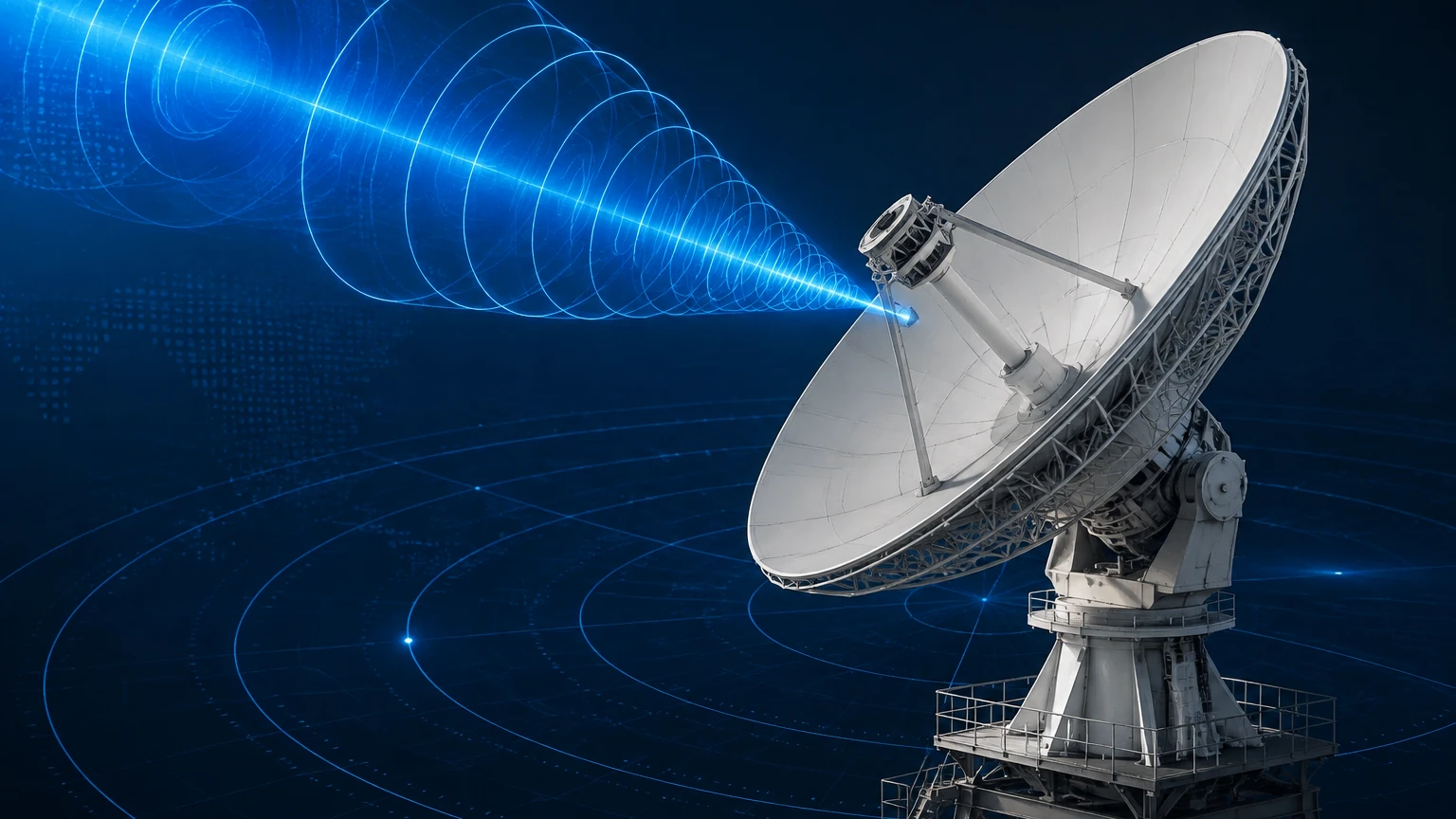
Radar transmitters utilize electromagnetic waves to determine the distance to a product surface. Unlike ultrasonic sensors, which rely on sound waves and are susceptible to air temperature and pressure changes, radar waves travel at the speed of light and are largely unaffected by the gas phase composition in a vessel. There are two primary methods used in industrial radar level measurement: Pulse Radar and Frequency Modulated Continuous Wave (FMCW).
Time of Flight (ToF) and Pulse Radar
Pulse radar transmitters emit short microwave pulses toward the target material. The instrument measures the time it takes for the pulse to travel to the surface and return to the sensor. Since the speed of light is constant, the distance is calculated using the formula:
*Distance = (Speed of Light × Time of Flight) / 2*.
This method is energy-efficient and suitable for many standard liquid applications. However, it may struggle with materials that have low reflectivity or in environments with significant surface turbulence.
Frequency Modulated Continuous Wave (FMCW)
FMCW radar transmitters emit a continuous signal with a constantly changing frequency. When the signal is reflected back, it is compared with the frequency being emitted at that exact moment. The difference between the transmitted and received frequencies is directly proportional to the distance. FMCW technology, particularly at higher frequencies like 80 GHz, offers superior resolution and signal-to-noise ratios, making it the preferred choice for complex applications involving solids or narrow tanks.
Guided Wave Radar (GWR)
While non-contact radar transmits waves through the air, Guided Wave Radar (GWR) utilizes a physical probe (rod or cable) to direct the microwave energy. The pulse travels along the probe, hits the product surface, and reflects back. GWR is highly effective for measuring liquids with low dielectric constants or in applications where heavy foam or steam would scatter a non-contact signal.
Key Evaluation Criteria for Radar Level Measurement
Selecting the correct radar transmitter requires an analysis of both the material being measured and the environment of the vessel. Engineers must consider the following factors to ensure long-term accuracy.
Frequency Bands
The frequency of the radar signal determines the beam angle and the instrument's ability to handle obstacles:
* 6 GHz (C-band): Primarily used for applications with heavy steam or foam, as the longer wavelength can penetrate these layers more effectively.
* 26 GHz (K-band): The "workhorse" of the industry, offering a balance between beam focus and signal strength. It is suitable for most liquid storage tanks.
* 80 GHz (W-band): The modern standard for high-precision measurement. It features a very narrow beam (often as small as 3°), allowing it to avoid internal tank obstructions like agitators or heating coils. It is also ideal for measuring solids where the surface may be uneven.
Dielectric Constant (εr)
The dielectric constant of the medium is the most critical factor in determining signal reflection. Materials with high dielectric constants, such as water (εr ≈ 80), reflect signals strongly. Hydrocarbons and oils often have low dielectric constants (εr < 2), which absorb more energy and reflect less, potentially requiring GWR or high-sensitivity FMCW transmitters.
Process Conditions
Welk radar solutions are designed to withstand extreme environments. Evaluation must include:
* Temperature: Standard sensors handle up to 150°C (302°F), while specialized high-temperature versions can exceed 450°C (842°F).
* Pressure: Applications ranging from vacuum to high-pressure reactors (up to 40 MPa or 400 bar) require specific flange and seal configurations.
* Corrosion: For aggressive chemicals, PTFE-coated antennas or flange-drop designs are necessary to protect the transmitter electronics.
Selection Guide and Practical Selection Table
Choosing between non-contact radar and guided wave radar depends on the physical constraints of the installation and the nature of the media. Use the following table as a preliminary engineering reference.
| Feature | 26 GHz Non-Contact Radar | 80 GHz Non-Contact Radar | Guided Wave Radar (GWR) |
| :— | :— | :— | :— |
| Best Use Case | Large liquid storage tanks | Narrow tanks, solids, small nozzles | Interface measurement, low dielectric liquids |
| Beam Angle | 8° to 20° | 3° to 8° | N/A (Directed along probe) |
| Accuracy | ±3 mm | ±1 mm | ±2 mm |
| Foam Resistance | Moderate | Low (unless high power) | High |
| Internal Obstacles | Requires clear path | Easily avoids obstacles | Unaffected if probe is clear |
| Maintenance | Very Low (No contact) | Very Low (No contact) | Low (Probe cleaning may be required) |
For a detailed review of specific models and technical support for your application, you can Review product options and application support on the Welk official site.
Installation Considerations and Best Practices
Even the most advanced radar transmitter will fail if installed incorrectly. Proper mounting ensures that the signal path is clear and the reflection is maximized.
1. Nozzle Height and Diameter: The antenna should ideally extend slightly beyond the nozzle to prevent "ringing" or false reflections from the nozzle walls. If using an 80 GHz transmitter, smaller nozzles (e.g., DN50 or 2") are often sufficient due to the narrow beam.
2. Avoid the Center: In tanks with domed roofs, do not install the transmitter in the exact center. This can cause multiple reflections to converge at the sensor, creating a false high-level reading. Position the sensor at roughly 1/2 to 1/3 of the tank radius from the wall.
3. Obstruction Clearance: Ensure the signal beam does not intersect with ladders, pipes, or agitator blades. If an obstruction is unavoidable, many modern transmitters offer "false echo suppression" software to map out and ignore these static reflections.
4. Inlet Proximity: Never install the transmitter directly above the product inlet. The turbulence and falling material will interfere with the signal and may cause erratic readings.
5. Orientation: For solid materials, an aiming flange (swivel holder) is often required to orient the beam toward the material's angle of repose, ensuring the maximum signal returns to the sensor.
Limitations and Common Challenges
While radar is highly versatile, it is not a universal solution for every process. Understanding its limitations is key to avoiding project failures.
* Heavy Foam: Extremely thick, dense foam (like shaving cream) can absorb the radar signal entirely. In these cases, GWR or hydrostatic pressure transmitters may be more reliable.
* Extremely Low Dielectric Media: In some liquefied gases with dielectric constants below 1.4, the reflection may be too weak for non-contact radar. GWR with a coaxial probe is the standard solution here.
* Blocking Distance (Dead Zone): All radar transmitters have a minimum measuring distance (typically 50 mm to 300 mm from the sensor face). If the material enters this zone, the reading becomes unreliable.
* Vacuum Conditions: While radar works in a vacuum, the sealing of the transmitter must be rated for it. High-vacuum applications require specialized glass-to-metal seals to prevent leakage into the electronics housing.
Frequently Asked Questions (FAQs)
Q: Can a radar transmitter measure through a plastic tank lid?
A: Yes. Since plastic is non-conductive and has a low dielectric constant, radar waves can pass through it. This allows for "non-invasive" measurement where the sensor is mounted outside a plastic IBC or storage tank.
Q: What is the difference between radar and ultrasonic level sensors?
A: Ultrasonic sensors use sound waves, which require a medium (air) and are affected by temperature, wind, and tank pressure. Radar uses electromagnetic waves, which work in a vacuum and are unaffected by most gas-phase conditions, making them more accurate for industrial processes.
Q: How often does a radar transmitter need calibration?
A: Because there are no moving parts and the speed of light is constant, radar transmitters are extremely stable. In most applications, they do not require periodic recalibration, though a functional check every 1–2 years is recommended for safety-critical loops.
Q: Can radar measure the interface between two liquids?
A: Guided Wave Radar (GWR) is specifically suited for this. If the upper liquid has a lower dielectric constant (like oil) and the lower liquid has a higher one (like water), the radar signal will reflect off both surfaces, allowing the transmitter to report both the total level and the interface level.
Conclusion
The radar transmitter represents a significant advancement in process control, offering a blend of precision and durability that few other technologies can match. By understanding the nuances of frequency selection, dielectric properties, and installation geometry, engineers can implement level measurement solutions that operate maintenance-free for years. For professionals seeking reliable, cost-effective, and accurate instrumentation, Welk provides a range of radar and ultrasonic solutions tailored to the rigors of modern industry. To explore the full technical specifications of our current lineup, visit our Main Page for comprehensive product data and engineering support.