Overhead Power Line Sensors
Overhead Power Line Sensors
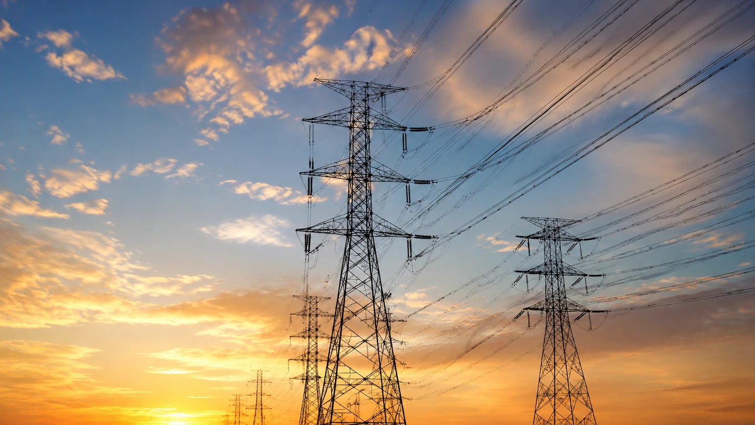
In the realm of modern utility management and industrial automation, the monitoring of transmission and distribution infrastructure has transitioned from periodic manual inspections to real-time automated data collection. Overhead power line sensors represent a critical category of industrial instrumentation designed to monitor the physical state, environmental conditions, and electrical performance of high-voltage conductors. These sensors are essential for implementing Dynamic Line Rating (DLR), preventing structural failures, and ensuring that safety clearances are maintained between conductors and the ground or surrounding vegetation.
From an engineering perspective, many overhead power line sensors function as specialized distance or "level" measurement devices. By measuring the distance between a conductor and a reference point, such as the ground or a support structure, operators can calculate conductor sag, which is directly influenced by current load and ambient temperature. Understanding the measurement principles, selection criteria, and installation requirements for these systems is vital for utility engineers and industrial facility managers.
Measurement Principles of Overhead Power Line Sensors
To accurately monitor overhead lines, sensors utilize various physical principles to detect distance, temperature, and current. When focusing on the physical positioning and sag of the lines, non-contact distance measurement technologies—similar to those used in industrial liquid level sensing—are most prevalent.
Radar (FMCW and Pulse)
Radar technology, particularly Frequency Modulated Continuous Wave (FMCW) radar, is a leading method for monitoring overhead power line clearance. The sensor emits a high-frequency electromagnetic wave (typically in the 24GHz or 80GHz band) toward the conductor or the ground. By measuring the frequency shift or the time of flight of the reflected signal, the device calculates the exact distance.
Radar is highly preferred in outdoor utility environments because electromagnetic waves are largely unaffected by air temperature, wind, rain, or fog. This ensures consistent accuracy across varying seasonal conditions. For power line applications, high-frequency 80GHz radar is often selected due to its narrow beam angle, which allows it to isolate a specific conductor without interference from nearby structures or other phases.
Ultrasonic Measurement
Ultrasonic sensors operate by emitting high-frequency sound pulses. The sensor measures the time it takes for the sound wave to travel to the target and echo back. While cost-effective, ultrasonic sensors are sensitive to environmental factors. The speed of sound changes with air temperature and humidity, requiring integrated compensation algorithms. In overhead power line sensors, ultrasonic technology is typically reserved for lower-voltage distribution lines or applications where the distance to be measured is relatively short (under 15 meters).
LiDAR and Laser Ranging
Light Detection and Ranging (LiDAR) uses laser pulses to map the distance to a target. These sensors provide extremely high resolution and can create a 3D profile of the conductor and surrounding vegetation. However, LiDAR can be sensitive to atmospheric obscuration such as heavy snow or dense smoke. In many utility applications, LiDAR is used for mobile inspections (mounted on drones or helicopters) rather than as a permanent pole-mounted monitoring solution.
MEMS Accelerometers and Inclinometers
Some overhead power line sensors are mounted directly onto the conductor. These devices use Micro-Electro-Mechanical Systems (MEMS) to measure the angle (tilt) and vibration of the line. By calculating the catenary curve based on the angle of the conductor at the attachment point, the system can infer the sag and ground clearance without a direct distance measurement to the ground.
Key Applications in Industrial and Utility Sectors
Conductor Sag and Clearance Monitoring
As conductors carry more current, they heat up and expand, causing them to sag. If a line sags too low, it risks an accidental discharge (arc) to the ground, vehicles, or vegetation. Overhead power line sensors provide continuous data to ensure that minimum safety clearances, as defined by standards like the National Electrical Safety Code (NESC), are never breached.
Dynamic Line Rating (DLR)
Traditional power lines are operated based on "Static Line Ratings," which assume worst-case weather conditions (high heat, no wind). This often results underutilizing the line's capacity. By using sensors to monitor real-time sag and ambient conditions, utilities can implement Dynamic Line Rating, safely increasing the amount of power transmitted through existing infrastructure when weather conditions allow for better cooling.
Vegetation Management
Overhead power line sensors can be calibrated to detect the proximity of tree branches. By monitoring the distance between the conductors and the surrounding canopy, utilities can prioritize trimming schedules based on actual encroachment risks rather than arbitrary time intervals.
Selection Criteria for Overhead Power Line Sensors
Choosing the correct sensor requires a balance between technical requirements and environmental constraints. Engineers should evaluate the following factors:
1. Measurement Range: The sensor must be capable of measuring the full span of potential movement, typically from 2 meters to over 50 meters, depending on the tower height and terrain.
2. Accuracy Requirements: For clearance safety, an accuracy of ±1 cm to ±5 cm is usually required. Radar-based systems generally provide the highest stability in this regard.
3. Power Supply: Since these sensors are often installed in remote locations, they must be low-power. Options include solar-powered units with battery backup or "energy harvesting" sensors that draw power directly from the magnetic field of the conductor they are monitoring.
4. Communication Protocols: Data must be transmitted to a central SCADA system or cloud platform. Common options include cellular (4G/5G), LoRaWAN, or satellite links for extremely remote areas.
5. Environmental Durability: Sensors must withstand extreme temperatures (-40°C to +85°C), UV exposure, and high-wind loads. An IP67 or IP68 rating is essential for long-term reliability.
Technology Comparison Table
| Feature | Radar (FMCW) | Ultrasonic | LiDAR / Laser | MEMS (Line-Mounted) |
| :— | :— | :— | :— | :— |
| Accuracy | High (±2-5mm) | Moderate (±10-20mm) | Very High (±1mm) | Indirect (Calculated) |
| Weather Resistance | Excellent | Poor (Wind/Temp sensitive) | Moderate (Fog/Rain sensitive) | Excellent |
| Measurement Range | Up to 100m+ | Up to 15m | Up to 200m+ | N/A (Angle based) |
| Installation | Pole/Structure Mounted | Pole Mounted | Pole/Drone Mounted | On-Conductor |
| Cost | Mid-High | Low | High | Moderate |
Installation and Safety Considerations
Installing overhead power line sensors involves significant safety protocols due to the proximity to high-voltage equipment.
* Safe Working Clearances: Installation must be performed by qualified personnel using insulated tools and maintaining Minimum Approach Distances (MAD). In many cases, sensors are installed on the support poles rather than the live wires to simplify maintenance and improve safety.
* Electromagnetic Interference (EMI): The high electromagnetic fields surrounding power lines can interfere with electronic circuitry. Sensors designed for this environment must have robust shielding and filtered power supplies to prevent data corruption or hardware damage.
* Mounting Stability: For ground-to-conductor distance measurement, the sensor must be mounted on a stable platform. Any vibration or shifting of the mounting bracket will result in measurement errors. Engineers often use specialized brackets that compensate for pole tilt.
* Calibration: Initial calibration should involve a manual measurement of the line height to establish a baseline. For ultrasonic sensors, the temperature probe must be shielded from direct sunlight to ensure accurate compensation calculations.
Limitations and Challenges
While overhead power line sensors significantly improve grid visibility, they are not without limitations.
* Signal Multipath: In dense urban environments or substations, radar signals may reflect off multiple surfaces (fences, buildings, transformers), leading to "ghost" signals. Advanced signal processing and narrow beamwidths are required to filter these out.
* Data Latency: In DLR applications, even a few minutes of data latency can be problematic during rapid weather changes. The communication network must be robust enough to handle the required sampling frequency.
* Maintenance Access: Replacing a faulty sensor on a high-voltage tower is expensive and requires specialized crews. Therefore, the Mean Time Between Failures (MTBF) is a critical metric for B2B procurement.
For organizations looking to integrate these technologies into broader industrial monitoring frameworks, reviewing comprehensive product options and application support is a necessary step. Detailed technical specifications for various sensing technologies can be found on the Main Page of professional instrumentation providers.
Frequently Asked Questions (FAQ)
Q: Can radar sensors be used on all types of conductors?
A: Yes, radar sensors detect the physical reflection of the conductor. As long as the conductor provides a sufficient "Radar Cross Section" (RCS), the sensor can track it. This applies to ACSR, AAC, and modern composite conductors.
Q: How do sensors handle multiple lines in a single corridor?
A: Higher-end sensors use narrow beam angles (e.g., 3° to 8°) to target a specific phase. Software filtering can also be used to distinguish between different distances if multiple lines are within the sensor's field of view.
Q: Are these sensors compatible with existing SCADA systems?
A: Most industrial-grade overhead power line sensors support standard protocols such as Modbus RTU, DNP3, or MQTT, allowing for seamless integration into existing utility control centers.
Q: What is the typical lifespan of a pole-mounted sensor?
A: A well-designed industrial sensor should have an operational life of 10 to 15 years, depending on the battery life and the harshness of the environmental conditions.
By implementing a robust array of overhead power line sensors, utilities can transition from reactive maintenance to a proactive, data-driven operational model. This not only enhances safety but also optimizes the existing infrastructure to meet the increasing demands of the modern electrical grid.