Water Tank Level Controller
Water Tank Level Controller
In industrial, municipal, and commercial water management, the water tank level controller serves as the central nervous system of fluid handling operations. Whether managing a cooling tower, a municipal reservoir, or a chemical processing tank, the ability to monitor and regulate liquid levels with precision is critical for operational efficiency, safety, and equipment longevity. A robust level control system prevents dry-running of pumps, avoids hazardous overflows, and ensures a consistent supply of water for downstream processes.
Selecting the appropriate water tank level controller requires a deep understanding of measurement physics, the environmental conditions of the tank, and the specific requirements of the application. This guide examines the primary technologies used in level measurement, selection criteria, and practical installation considerations for engineering professionals.
Measurement Principles for Level Control
Before selecting a controller, it is essential to understand the physics behind the sensors that provide the data. Modern industrial systems utilize several distinct technologies, each with specific advantages and limitations.
1. Ultrasonic Level Measurement
Ultrasonic sensors are non-contact devices that emit high-frequency sound waves (typically 20 kHz to 200 kHz). The sensor measures the time it takes for the pulse to travel to the water surface and return as an echo. Since the speed of sound in air is relatively constant (dependent on temperature), the distance to the water surface is easily calculated.
* Advantages: No moving parts, non-contact (ideal for corrosive or wastewater), and relatively low cost.
* Limitations: Performance can be affected by heavy foam, steam, or significant temperature fluctuations that change the speed of sound.
2. Radar (Microwave) Level Measurement
Radar level meters operate on a similar principle to ultrasonic sensors but use electromagnetic waves instead of sound. These waves travel at the speed of light and are reflected by the dielectric constant of the water surface.
* Advantages: Highly accurate (up to ±1 mm), unaffected by vacuum, pressure, temperature, or vapor. It is the preferred choice for high-precision industrial applications.
* Limitations: Generally higher initial cost than ultrasonic or hydrostatic options.
3. Hydrostatic Level Measurement
Hydrostatic transmitters measure the pressure exerted by the liquid column above the sensor. In an open tank, the pressure at the bottom is directly proportional to the height of the water (Pressure = Density × Gravity × Height).
* Advantages: Simple installation (submersible or externally mounted), reliable in deep tanks, and unaffected by surface turbulence or foam.
* Limitations: Accuracy depends on constant liquid density; if the water temperature or salinity changes significantly, the density—and thus the reading—will shift.
4. Magnetic Level Gauges and Switches
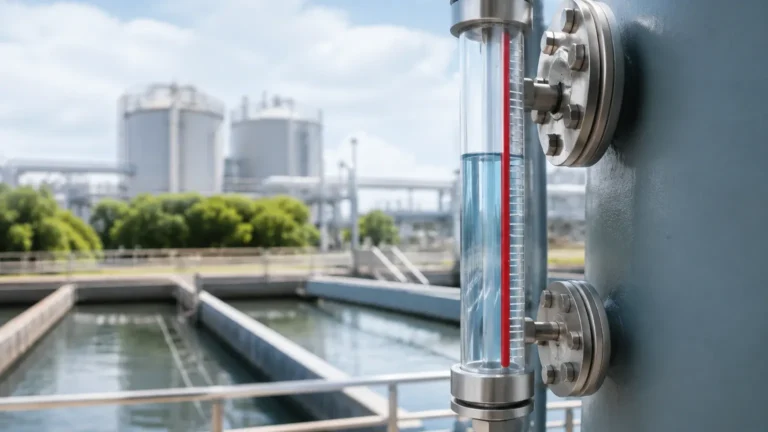
Magnetic gauges use a float containing a magnet that moves with the water level inside a bypass chamber. This magnet actuates external flags for visual indication and can trigger reed switches for point-level control.
* Advantages: Provides both a local visual reading and an electrical signal; requires no power for the visual component.
* Limitations: Mechanical components are subject to wear or fouling if the water contains high levels of debris or scale.
Key Components of a Level Control System
A complete water tank level controller system typically consists of three main elements:
1. The Sensing Element: The radar, ultrasonic, or hydrostatic transmitter that generates a signal (typically 4-20mA, RS485, or Hart protocol).
2. The Controller/Indicator: A digital panel meter or PLC (Programmable Logic Controller) that interprets the signal. This unit allows the user to set specific "Set Points" (e.g., High-High, High, Low, and Low-Low).
3. The Actuator: The final control element, such as a solenoid valve, a motorized valve, or a Variable Frequency Drive (VFD) for a pump, which physically adjusts the water level based on the controller's commands.
Technical Selection Criteria
Choosing the right technology depends on the specific parameters of the installation. Engineers should evaluate the following factors before finalizing a specification:
Media Characteristics
Is the water clean, or does it contain solids? For clean water, almost any technology works. For wastewater or sludge, non-contact methods like ultrasonic or radar are preferred to prevent sensor fouling. If the water is stored under high pressure or at high temperatures, radar is often the only reliable choice.
Tank Geometry and Environment
* Tank Height: Hydrostatic sensors are excellent for very deep tanks (over 20 meters), while ultrasonic sensors are often capped at 10-15 meters for reliable performance.
* Internal Obstructions: If the tank has internal ladders, agitators, or heating coils, radar with a narrow beam angle or "false echo suppression" is necessary to avoid interference.
* Outdoor vs. Indoor: Outdoor tanks subject to direct sunlight may require temperature-compensated ultrasonic sensors or radar to maintain accuracy.
Comparison Table: Level Measurement Technologies
| Technology | Contact Type | Accuracy | Max Range (Typical) | Best For |
| :— | :— | :— | :— | :— |
| Ultrasonic | Non-Contact | ±0.25% to 0.5% | 15 meters | Clean water, wastewater, open channels |
| Radar | Non-Contact | ±1 mm to 3 mm | 30+ meters | Process tanks, steam, high precision |
| Hydrostatic | Contact | ±0.1% to 0.5% | 200 meters | Deep wells, reservoirs, vented tanks |
| Magnetic | Contact | ±5 mm to 10 mm | 6 meters | Visual monitoring, high-pressure boilers |
Installation and Configuration Best Practices
Proper installation is as critical as sensor selection. Even the most advanced water tank level controller will fail if the sensor is incorrectly positioned.
1. Avoid the "Dead Zone": Every non-contact sensor has a "blocking distance" or dead zone near the face of the transducer (typically 0.2m to 0.5m). The sensor must be mounted high enough so that the maximum water level never enters this zone.
2. Positioning Relative to Inflow: Never mount a level sensor directly above the water inlet. The turbulence and bubbles created by incoming water will cause erratic readings and signal loss.
3. Stilling Wells: In tanks with heavy agitation or surface waves, a stilling well (a perforated pipe) can be used to provide a calm surface for the sensor to measure.
4. Cable Protection: For hydrostatic submersible sensors, ensure the vented cable is not kinked. The vent tube allows the sensor to compensate for changes in atmospheric pressure; if it is blocked, the level reading will be inaccurate.
Limitations and Common Engineering Challenges
While modern controllers are highly reliable, engineers must account for specific environmental risks:
* Condensation: In humid environments, water droplets can form on the face of ultrasonic transducers, dampening the signal. Some sensors feature specialized coatings or "drip-off" designs to mitigate this.
* Vapor and Dust: Heavy steam or dust can attenuate ultrasonic signals. In these cases, 80GHz high-frequency radar is recommended, as it can penetrate these atmospheric conditions with minimal signal loss.
* Power Surges: Level controllers are often connected to long cable runs, making them susceptible to lightning strikes or industrial electrical noise. Using shielded cables and surge protection modules is standard practice for industrial installations.
Frequently Asked Questions (FAQ)
Q: Can I use one controller for multiple tanks?
A: Yes, many modern multi-channel controllers can accept signals from several sensors simultaneously. However, for critical safety applications, independent controllers for each tank are recommended to prevent a single point of failure.
Q: How often do level sensors need calibration?
A: This depends on the technology. Hydrostatic sensors may drift slightly over years and should be checked annually. Radar and ultrasonic sensors are generally more stable but should be verified during routine maintenance cycles.
Q: What is the difference between a level transmitter and a level switch?
A: A level transmitter provides continuous measurement (e.g., 0% to 100% full), allowing for precise control. A level switch is a point-level device that only triggers when the water reaches a specific height (e.g., an overflow alarm).
Conclusion
Implementing an effective water tank level controller system is a balance of selecting the right physics for the media and ensuring the installation environment supports the technology. By understanding the trade-offs between ultrasonic, radar, and hydrostatic methods, engineers can design systems that provide years of maintenance-free service. For those looking to specify equipment for a new project or upgrade an existing facility, you can Review product options and application support to find the exact configuration required for your industrial needs.
Whether the goal is simple pump automation or complex process integration, the accuracy of the level data is the foundation of the entire control loop. Investing in high-quality instrumentation and following rigorous installation standards ensures that water management remains a predictable and reliable part of industrial operations.