Continuous Fluid Level Sensor
Continuous Fluid Level Sensor
In industrial process control, the ability to monitor the volume of liquids in real-time is fundamental to operational safety, inventory management, and efficiency. A continuous fluid level sensor differs from point level switches by providing a constant signal output—typically 4-20mA, 0-10V, or digital protocols like HART or RS485—that represents the exact level of the fluid at any given moment. Whether managing a water treatment facility, a chemical processing plant, or oil storage, selecting the appropriate technology requires a deep understanding of physics, fluid dynamics, and environmental constraints.
Understanding Continuous Level Measurement
Continuous level measurement provides a seamless data stream across the entire span of a vessel. This allows operators to calculate flow rates, detect gradual leaks, and optimize pump cycles. Unlike point level sensors that only indicate if a tank is "full" or "empty," a continuous fluid level sensor enables sophisticated automation. For instance, in a chemical reactor, maintaining a precise volume is often critical to the reaction kinetics. In such cases, the sensor acts as the primary feedback loop for the control system.
Before selecting a sensor, it is essential to understand the primary measurement principles used in modern industry. Each technology interacts with the fluid and the surrounding environment differently, influencing its accuracy and reliability.
Core Measurement Principles and Technologies
Radar Level Measurement (Non-contact and Guided)
Radar technology is widely considered the gold standard for high-accuracy continuous measurement. It operates on the Time-of-Flight (ToF) principle, where electromagnetic pulses are emitted toward the fluid surface and reflected back to the sensor.
* Non-Contact Radar: These sensors emit microwave signals (often at 26GHz or 80GHz) through the air. The higher the frequency, the narrower the beam angle, which helps avoid internal tank obstructions like agitators or ladders. Because radar waves do not require a medium for propagation, they are unaffected by vacuum, high pressure, or temperature fluctuations.
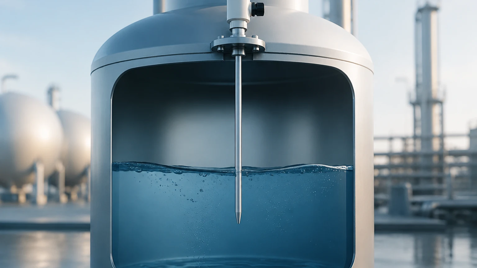
* Guided Wave Radar (GWR): GWR uses a physical probe (cable or rod) to guide the microwave signal to the liquid surface. This is particularly effective for fluids with low dielectric constants (like oils) or in applications with heavy foam, as the probe concentrates the signal energy, ensuring a stronger reflection.
Ultrasonic Level Sensors
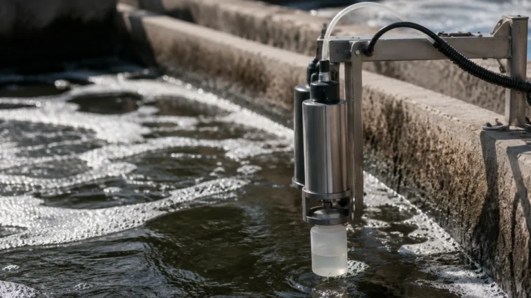
Ultrasonic sensors also use the ToF principle but rely on sound waves rather than electromagnetic waves. The sensor emits an ultrasonic pulse that bounces off the liquid surface and returns to the transducer. The distance is calculated based on the speed of sound.
While cost-effective, ultrasonic sensors are sensitive to the medium through which the sound travels. They require temperature compensation because the speed of sound changes with air temperature. They are generally unsuitable for vacuum applications or environments with high levels of dust, heavy vapor, or acoustic noise.
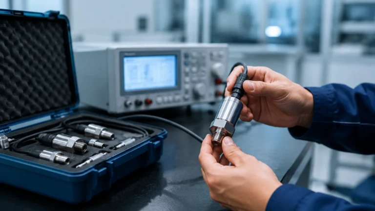
Hydrostatic Pressure Transmitters
Hydrostatic measurement is based on the principle that the pressure at the bottom of a liquid column is directly proportional to the height of the liquid and its density ($P = \rho \cdot g \cdot h$). These sensors can be submersible (dropped into the tank) or externally mounted via a flange or thread at the bottom of the vessel.
This method is highly reliable for open tanks or vented vessels where the fluid density remains constant. However, if the fluid density changes due to temperature shifts or chemical composition, the sensor must be recalibrated or paired with a second pressure sensor for differential measurement in pressurized tanks.
Magnetic Level Gauges and Magnetostrictive Sensors
Magnetic level gauges use a float containing an internal magnet that moves with the liquid level inside a bypass chamber. For continuous electronic output, a magnetostrictive sensor is often mounted to the outside of the chamber. As the float moves, the sensor detects the magnetic field and provides a high-precision level reading (often with accuracy up to 0.1mm). This is a robust solution for high-pressure and high-temperature applications where direct contact with the electronics is undesirable.
Selection Criteria for Industrial Applications
Choosing the right continuous fluid level sensor involves more than just matching a probe length to a tank height. Engineers must evaluate the following factors:
1. Chemical Compatibility: The sensor materials (316L stainless steel, PTFE, PVDF, etc.) must withstand the corrosivity of the fluid. For example, hydrochloric acid requires plastic-wetted parts or specialized coatings.
2. Dielectric Constant (εr): For radar sensors, the dielectric constant of the fluid determines how much energy is reflected. Water has a high εr (~80), making it easy to detect, while hydrocarbons may have an εr as low as 1.4, requiring more sensitive radar or GWR.
3. Process Conditions: High-pressure vessels (above 40 bar) or extreme temperatures (above 200°C) often disqualify ultrasonic sensors, leaving radar or magnetic gauges as the primary options.
4. Tank Geometry: Narrow tanks or tanks with internal cooling coils require sensors with narrow beam angles (like 80GHz radar) to prevent "false echoes" from the tank walls or internals.
5. Surface Turbulence and Foam: If the liquid surface is turbulent due to an agitator, ultrasonic signals may scatter. GWR or hydrostatic sensors are generally more stable in these conditions.
Comparative Selection Table
| Technology | Accuracy | Media Suitability | Best For | Limitations |
| :— | :— | :— | :— | :— |
| Non-contact Radar | ±1mm to ±5mm | Most liquids/solids | Corrosive, high-temp, high-pressure | Low dielectric fluids |
| Guided Wave Radar | ±2mm | Liquids, interfaces | Low dielectric, foam, small tanks | Contact with media required |
| Ultrasonic | ±0.25% of range | Water, wastewater | Open channels, non-corrosive liquids | Affected by vapor, foam, vacuum |
| Hydrostatic | ±0.1% to ±0.5% | Clear liquids, slurries | Deep wells, vented tanks | Density must be constant |
| Magnetostrictive | ±0.1mm | Clean liquids | High precision, custody transfer | Float can get stuck in dirty fluids |
Installation and Engineering Best Practices
Correct installation is as critical as sensor selection. Even the most advanced continuous fluid level sensor will fail if improperly positioned.
* Avoid the Fill Stream: Never install a sensor directly above the point where fluid enters the tank. The turbulence and the falling liquid will cause erratic readings.
* The "Dead Zone" (Blocking Distance): All ToF sensors (radar and ultrasonic) have a minimum distance near the sensor face where they cannot measure. Ensure the sensor is mounted high enough so the maximum fluid level does not enter this zone.
* Stilling Wells and Bypass Chambers: For extremely turbulent surfaces or fluids with heavy foam, installing the sensor inside a stilling well (a vertical pipe) can provide a calm surface for measurement. This is common in oil and gas applications.
* Orientation and Leveling: For ultrasonic and non-contact radar, the sensor must be mounted perfectly perpendicular to the liquid surface to ensure the signal reflects directly back to the transducer.
* Cable Management: For hydrostatic sensors, use vented cables to allow the sensor to compensate for changes in atmospheric pressure. Ensure the vent tube is protected from moisture ingress using a desiccant filter.
Operational Limitations and Risk Mitigation
While continuous fluid level sensors are highly reliable, certain risks must be managed:
* Build-up and Scaling: In many chemical processes, material can build up on the sensor probe or face. While radar is somewhat resistant to this, heavy scaling can eventually attenuate the signal. Regular inspection or the use of non-contact sensors with self-cleaning purge connections is recommended.
* Vapor and Condensation: Heavy steam or chemical vapors can attenuate ultrasonic signals. In these environments, radar is the preferred choice because microwaves penetrate vapor easily.
* Signal Interference: In large metal tanks, multiple reflections can occur. Modern sensors include "false echo suppression" software, allowing the user to map out internal obstructions so the sensor ignores them.
For engineers seeking to optimize their process with reliable instrumentation, it is helpful to consult technical specifications and application notes. You can Review product options and application support to find the specific configuration that matches your industrial requirements.
Frequently Asked Questions (FAQs)
Q: Can one sensor type work for all fluids?
No. While radar is very versatile, it may not be the most cost-effective for simple water tanks where an ultrasonic or hydrostatic sensor would suffice. Conversely, hydrostatic sensors fail if the liquid density is not consistent.
Q: How does foam affect continuous level measurement?
Foam is a major challenge. Ultrasonic waves often get absorbed by foam, leading to a "lost signal" error. Non-contact radar may reflect off the top of the foam or pass through it, depending on the foam's density and moisture content. GWR is typically the most reliable choice for foamy applications.
Q: What is the difference between 2-wire and 4-wire sensors?
2-wire sensors are loop-powered, meaning the same two wires carry both the power and the 4-20mA signal. They are easier to install but have limited power for advanced processing. 4-wire sensors have separate power and signal lines, allowing for more power-intensive features like heated displays or high-power transducers.
Q: How often do these sensors need calibration?
This depends on the technology. Radar and ultrasonic sensors are generally "set and forget" unless the process conditions change significantly. Hydrostatic sensors may require annual calibration to account for any drift in the pressure diaphragm.
Q: Can these sensors be used in hazardous areas?
Yes, most industrial continuous fluid level sensors are available with ATEX, IECEx, or UL certifications for use in explosive atmospheres. These typically require intrinsic safety (Ex i) or explosion-proof (Ex d) installation methods.
By carefully matching the measurement principle to the specific fluid and vessel characteristics, industrial operators can ensure long-term accuracy and safety in their level monitoring processes.